Problems with the cutting deck

Bange

Well-Known Member
Joined
Mar 28, 2021
Threads
14
Messages
253
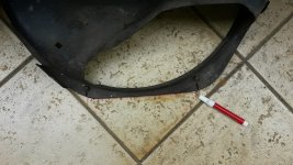
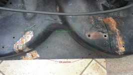
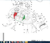
I removed the support on the left side (red) and repositioned it closer to the right, so as not to hit the bottom anymore, keeping the same height as the holes on the right (green).
However, as can be seen in the drawing, it was not parallel to the rear structure of the deck and, in addition, the tire scrapes the deck when turning to the left side.
I will have to change the structure of the left support (red) to position it parallel to the right support (green), keeping the holes the same height.
m_Primeira tentativa.jpg
 

Bange

Well-Known Member
Joined
Mar 28, 2021
Threads
14
Messages
253
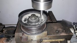
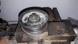
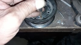
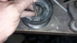
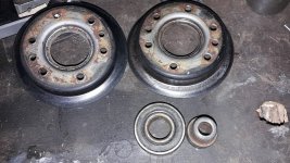
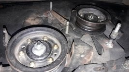
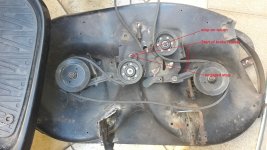
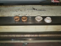
While the idea of changing the geometry of the deck matured, I changed the bearings of the idler pulley and the tension pulley... both were dry, noisy but without significant play.
m_20230512_175540.jpgm_20230512_175812.jpgm_20230512_181409.jpgm_20230512_181448.jpgm_20230512_182058.jpgm_20230512_215911.jpg
 

Bange

Well-Known Member
Joined
Mar 28, 2021
Threads
14
Messages
253
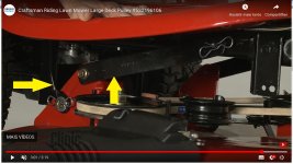
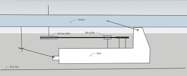
Hello everyone... anyone "online" and who has a deck like the one below (same suspension arm and link) to tell me at what level (1, 2...6) the belt is perfectly horizontal... with respect to the driving pulley.
m_Tipo de braço de superte.jpg
 

Bange

Well-Known Member
Joined
Mar 28, 2021
Threads
14
Messages
253
Guys, I don't know if you understand, but what I need to know is what level is indicated when the belt is as shown in the drawing, that is, perfectly horizontal.
...and can be any similar type of deck...
m_Alinhamento horizontal da correia.jpg
 

Bange

Well-Known Member
Joined
Mar 28, 2021
Threads
14
Messages
253
I analyzed the situation of my deck a lot and came to some conclusions...
1 - It's a poorly made adaptation of a Husqvarna deck, on a Murray product. (obvious)
2 - The suspension arms must be the same size, which is why my deck twisted when going up or down.
3 - The distance from the deck towers (where the suspension arms connect) were too far apart, which is why it hit the bottom of the fender and still made it difficult to engage level 6 in height.
4 – I was wrong in imagining parallelism of the towers in relation to the end of the deck... yes, it is possible to do it, but the geometry and the distances interfere either in the front left tire with the deck (when turning to the left) or in the tensioner pulley with a right draglink (if you use the smaller arm that came with the suspension) or on the deflector (which, when open to place the tube, must be vertical) and also on the connection of the discharge tube in its complement to the collector's basket.

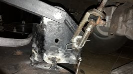
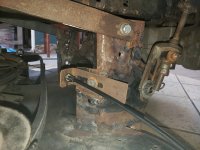
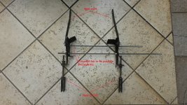
As I don't have any references with measurements, I attached the towers with two threaded bars with a distance slightly greater than the width of the chassis, so as not to hit the fender at the highest height of the deck.
I made two suspension bars of the same size as the larger one that came on the tractor.
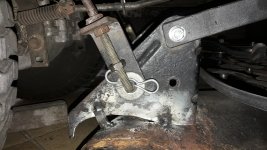
I modified the arms that lift the deck (I didn't like the original design), fixed the arms on the towers and these to the arms and lift... I put the lever in position 6.
I placed the deck under the tractor and observed the best position (imagining it high and low) so as not to interfere with anything (tire, draglink, pulleys, deflector, discharge tube...), when I arrived at a position that seemed ideal to me , I lowered the lever to level 1, marked them on the deck and made punctual and temporary welds, as the left one did not even touch the deck and the right one only in two points (the geometry was very compromised, not following the curvature of the deck) .
I connected the front link, and the deck now goes up and down without interfering at all and also doesn't spin like before.
Now it's time to create a point to fix and adjust the hitch cable and buy a strap that meets the new distance, as the previous one was short.
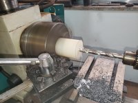
I also redid pins and put bushings that were already worn out in some places… only later will I be able to assess whether the tension pulley trepidation continues or not.

Parts made or remade:
m_20230519_125929 (mod).jpg

Marks on the floor so as not to lose the reference:

m_20230519_115201.jpgm_20230519_115135.jpg

Marks on the deck:
m_20230519_115907 (mod).jpgm_20230519_115231.jpg

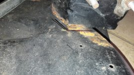
Temporary welds:
m_20230521_201957.jpgm_20230521_201932.jpg

Deck now lifts 8cm and has 1.8cm variance (front/rear).
But nothing is so good that it can't be improved...
 

Bange

Well-Known Member
Joined
Mar 28, 2021
Threads
14
Messages
253
Do you think that a 3mm variation is good or is it still too big?
...at least on paper it worked...
 

Bange

Well-Known Member
Joined
Mar 28, 2021
Threads
14
Messages
253
Hello friends!
To determine the new belt size, I need to know where exactly the idler pulley works...whether in the engaged stop or in the middle between the start of the brake release.
Would anyone know how to tell?

m_20230524_105254 (1).jpg
 
Last edited:

Bange

Well-Known Member
Joined
Mar 28, 2021
Threads
14
Messages
253
Well friends,
Today I finished the adaptation project… it turned out really well.
The deck now rises and falls with virtually no forward or backward variation and no twisting.
I put a belt tension adjustment point (which I didn't have), replaced some coupling lever bushings... but the tensioner pulley still shakes a little, especially at low rpm.
I don't know if the lack of the keeper belt has anything to do with it, but now with the adjustment of the belt tension I could verify that with lower tension, the tensioner pulley vibrates less, but it is at a very critical point, because if it stays calm, I notice that the speed of the blades decreases, which means that the belt is slipping.
m_20230606_083736.jpgm_20230605_155325.jpgm_20230605_182112.jpg
 

Bange

Well-Known Member
Joined
Mar 28, 2021
Threads
14
Messages
253
Do you believe this vibration is acceptable?
 
Top