John Deere ZTRak 375 Battery Charging issues

Joined
Oct 13, 2021
Threads
2
Messages
18
1-season-old JD ZTRak with a Briggs 25 horse. I removed the battery over the winter and stored it in the basement. (I never recharged it but have come to learn a trickle charge was needed so I have since purchased one.) So this spring I placed factory battery back into service and it fired right up and started weekly from April-Sept with weekly cuts. Then all of a sudden the factory issue battery just died. So I bought a new Die Hard from auto parts store and placed it into service. I tested it with my Klein MM600 today and noticed it reads 12.25 volts after 1.5 hours in service which seems very low to me. id like to check the stator output but noticed it’s a 1-wire yellow coming down out of shroud to the voltage regulator and single red going from VR to the battery. Not sure how I can test the stator output without a two-wire lead. Any direction will be greatly appreciated. Also I don’t have the Briggs model number with me at the moment if that’s important to have. I can follow directions if anyone has the sequence and multimeter settings so I don’t blow it up.
 

bertsmobile1

Lawn Royalty
Joined
Nov 29, 2014
Threads
64
Messages
24,647
Unplug the yellow wire start the engine & run full speed
AC volts between the yellow wire & engine should be higher than 28V
Plug the yellow wire back in and unplug the red wire
Should be DC 13 V or better between the wire & the engine
Check the body of the rectifier to engine , should read 0 Ω.
If not locate the ground strap connected to the mounting bolt which will be broken somewhere ,
IF it is bad then make a new one and test the red wire again.
 
Joined
Oct 13, 2021
Threads
2
Messages
18
Unplug the yellow wire start the engine & run full speed
AC volts between the yellow wire & engine should be higher than 28V
Plug the yellow wire back in and unplug the red wire
Should be DC 13 V or better between the wire & the engine
Check the body of the rectifier to engine , should read 0 Ω.
If not locate the ground strap connected to the mounting bolt which will be broken somewhere ,
IF it is bad then make a new one and test the red wire again.
Thanks Bertsmobile. i will conduct the check list on Saturday…sorry to ask dumb questions but just confirming that my MM should be on “AC” and use red test lead to test the yellow wire coming down from stator…correct? And switch to “DC”and use the red test lead when testing the red wire. Correct? Also does it matter where on the rectifier I test for ohm/continuity? Thanks for your response above…appreciated
 

ILENGINE

Lawn Pro
Joined
May 6, 2010
Threads
39
Messages
9,855
Thanks Bertsmobile. i will conduct the check list on Saturday…sorry to ask dumb questions but just confirming that my MM should be on “AC” and use red test lead to test the yellow wire coming down from stator…correct? And switch to “DC”and use the red test lead when testing the red wire. Correct? Also does it matter where on the rectifier I test for ohm/continuity? Thanks for your response above…appreciated
Correct. But you will need to check the red wire on the mower side of the regulator because the red wire on the regulator may not have any output depending on style of regulator because some require battery voltage input to the regulator to close the internal switches to allow battery charging.

Also before going through the stator regulator testing try testing the voltage at the battery with the mower running full throttle and see what the voltage at the battery is. 13.5 or so at the battery means it is charging.
 
Joined
Oct 13, 2021
Threads
2
Messages
18
Correct. But you will need to check the red wire on the mower side of the regulator because the red wire on the regulator may not have any output depending on style of regulator because some require battery voltage input to the regulator to close the internal switches to allow battery charging.

Also before going through the stator regulator testing try testing the voltage at the battery with the mower running full throttle and see what the voltage at the battery is. 13.5 or so at the battery means it is charging.
Yes I did check the battery today at full throttle and it actually tested lower than 12.25…it was something like 12.15V
 
Joined
Oct 13, 2021
Threads
2
Messages
18
Unplug the yellow wire start the engine & run full speed
AC volts between the yellow wire & engine should be higher than 28V
Plug the yellow wire back in and unplug the red wire
Should be DC 13 V or better between the wire & the engine
Check the body of the rectifier to engine , should read 0 Ω.
If not locate the ground strap connected to the mounting bolt which will be broken somewhere ,
IF it is bad then make a new one and test the red wire again.
Ok here’s the results of your prescription.
1. Checked stator Voltage first. THIS TESTED AT 47 AC VOLTS.
2. Checked DC Voltage BACK to the battery. THIS TEST SHOWED 12.2V. Then turned motor ON at FULL throttle. THIS TEST SHOWED 12.13V.
3. Then checked Voltage Regulator ground.
Check VR for proper ground. THIS TEST SHOWED “OL” plus and intermittent beeping and a range of numbers that fluctuated between 2.6 and 10.0. This test never fell below 1.6 with a constant tone sounding.

Any ideas on what I should do next?
 

bertsmobile1

Lawn Royalty
Joined
Nov 29, 2014
Threads
64
Messages
24,647
AC 47 volts is good so the stator is OK
If you have the voltage regulator that is screwed into the dip stick tube, make up a wire with a ring terminal at both ends
One end bolted to the engine and the other under the head of the bolt that holds the rectifier on.
When the bigger VR is fitted with 2 bolts I make a ground strap for each bolt
Then check the DC voltage from the red wire to the engine when running full speed
If it is less than the battery voltage engine off then the regulator is cactus
If it is more than the battery voltage engine off but the voltage across the battery terminals is lower than the voltage at the red wire then the red wire is broken some where between the regulator & the battery
 
Joined
Oct 13, 2021
Threads
2
Messages
18
Ok here’s the results of your prescription.
1. Checked stator Voltage first. THIS TESTED AT 47 AC VOLTS.
2. Checked DC Voltage BACK to the battery. THIS TEST SHOWED 12.2V. Then turned motor ON at FULL throttle. THIS TEST SHOWED 12.13V.
3. Then checked Voltage Regulator ground.
Check VR for proper ground. THIS TEST SHOWED “OL” plus and intermittent beeping and a range of numbers that fluctuated between 2.6 and 10.0. This test never fell below 1.6 with a constant tone sounding.

Any ideas on what I should do next?
P.S. I would check the ground strap as you recommended but don’t know where to look for that. Please advise and I will check it.
AC 47 volts is good so the stator is OK
If you have the voltage regulator that is screwed into the dip stick tube, make up a wire with a ring terminal at both ends
One end bolted to the engine and the other under the head of the bolt that holds the rectifier on.
When the bigger VR is fitted with 2 bolts I make a ground strap for each bolt
Then check the DC voltage from the red wire to the engine when running full speed
If it is less than the battery voltage engine off then the regulator is cactus
If it is more than the battery voltage engine off but the voltage across the battery terminals is lower than the voltage at the red wire then the red wire is broken some where between the regulator & the battery
the VR on this model JD is bolted directly to a metal shroud that is bolted to engine body…it’s not bolted to dipstick tube
 
Joined
Oct 13, 2021
Threads
2
Messages
18
I just read in the Briggs & Stratton alternator/charging manual I found online that “there is NO bench test for the voltage regulator.” I find that hard to believe so I am checking with the forum experts…is this true?
 

StarTech

Lawn Royalty
Top Poster Of Month
Joined
Feb 19, 2020
Threads
75
Messages
10,104
Typically no you cant them on the bench. They must tested in a live circuit. This because you can not access the discrete components. Most everything is encapsulated in epoxy.

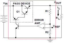
Here is example of a voltage regulator. Everything inside the red box is encapsulated; unless, it is mounted on a circuit with discrete components. Also in the case of the Briggs regulators they have rectifiers changing the stator AC output into a pulsing DC voltage. You particular engine's IPL show a single wire stator which means half wave rectification is being done. If you had a two wire stator then full wave rectification would done. This is also inside the voltage regulator module.

The following only the regulations portion of these modules.
1634495920647.png
 
Top