18 HP B&S Charging System

GoHardrGoHome

Member
Joined
Apr 26, 2019
Threads
2
Messages
21
Ok, I went out and stripped back the shrink tube on the wiring and actually found two diodes connected in series. One very near the engine and the other about one foot away.
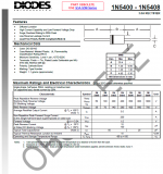
With the engine off, I checked both diodes individually and they only allow current in the direction of the battery. I tried to identify the diodes but only found numbers on Diode No. 2 (see attached diagram). With engine running at about 1/2 throttle, I then checked the voltage at the battery.
On the DC scale it was fluctuating between 2 and 15.5 VDC. I then decided to check it on AC scale just out of curiosity... 34 to 190 VAC!!
After running for about 5 minutes the diodes were very warm to the touch.
 

Attachments

  • Wiring Diagram.pdf
    214 KB · Views: 29

Richard Milhous

Well-Known Member
Joined
Aug 2, 2021
Threads
6
Messages
173
I'm no electrical engineer but I'm guessing at least one diode is fried like an egg. Keep in mind you can test them for resistance at 9V or whatever your tester supplies but the response may be non-linear. I.e., it looks fine on the tester but the 40V peak from the stator might blow right through.

I don't really know how meters measure AC or modulated DC voltage, but it's not simple to measure the effective (RMS) voltage. AC meter measurements on a non-sinusoidal or DC-biased voltage might be worthless.

It is quite possible the diodes are meant to dissipate a lot of heat, so that might be normal - but heat also reduces their service life.

I dunno for sure why this was designed to produce 28V AC RMS, but it's not improbable that a diode (or maybe even something else) has a dampening function: non-linear resistance, clamping, or more likely just ballast resistance. Otherwise the system is effectively operating at 22V RMS with the battery charged. Which is a lot, and might be to ensure the battery doesn't run dead if the engine is running slowly.

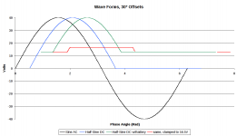
Why I think the diodes might be taking a lot of heat: Below is a graph of different theoretical systems. Each is offset by 30° for comparison. The black line shows a sinusoidal voltage at 28V RMS (approximately what your stator is cranking). The blue line shows the same curve interrupted by a perfect diode (infinite resistance in one direction, zero resistance in the other) with nothing else connected. The green line shows the voltage you would see from the same curve connected to a fully charged battery. The red line shows the same with the instantaneous voltage capped at 16.5V, which would produce a RMS voltage of 14.2 (I don't know how effective a multimeter is at reading RMS voltage for a pulsed DC circuit though).

The unlimited green curve would deliver about 27x the heat to a charged battery as the limited red curve, and about quadruple the power to a static load. My supposition is that something (probably one of the diodes) is supposed to limit the effective voltage.

If there are two diodes in series, there's a reason. Could this be aftermarket work? Or is it because they needed two diodes to handle the 40V peak voltage, and if one is fried the other will soon follow?
 

Attachments

  • Wave Forms.png
    Wave Forms.png
    37.4 KB · Views: 3

GoHardrGoHome

Member
Joined
Apr 26, 2019
Threads
2
Messages
21
Thanks very much for your input, Richard. If you're not an electrical engineer, you are definitely way above my pay grade on all of this!
I had the unit at a shop once to have a look at the issue and I don't know if they added an extra diode or what they did. I questioned them about it but the guy who worked on the mower doesn't work there anymore:(
I tried contacting B&S about the issue but was directed back to my local dealer. In the parts manual it only shows one diode so that is what is confusing me since the shop must have added a second one to the harness.
This is why, if there is a way to replace the diodes with a regulator rectifier, I would jump at the opportunity to buy one!
.... or, if someone could confidently direct me to exactly what was needed for diode(s) and tell me if they should be hooked up in series or parallel if more than one is required, then I'd buy some and get them installed.
B&S don't sell the diode as a separate part and I don't want to have to order a new stator in order to get the diode!
Thanks to all for your input:)
 

slomo

Lawn Pro
Joined
Jul 14, 2019
Threads
78
Messages
5,084
Someone needs to find the spec on the charging coil. Looking for rated amperage output spec.

That IN5406 diode is only rated at 3 amps of current. Hope this doesn't have disco headlights and ghetto blaster boom boxes on it.

Sounds like the wire protection is removed. Follow the charge wire with your fingers and your eyes. See if there is any form of wire damage.

I would keep any shrink wrap, plastic wire loom or electrical tape away from the diodes. Any covering will insulate the parts causing over heats leading to early parts failure.

Example. Someone finds the coil puts out 4 amps. Get an 8-15 amp rated diode.

Only need one or can parallel to keep part size down and handle more current.
 

bertsmobile1

Lawn Royalty
Joined
Nov 29, 2014
Threads
65
Messages
24,995
Well the current draw for a flat battery and an electric clutch would be well over 3 Amps .
However once again why?
Now one could strip & rewind a B & S stator if one was desperate but for all pracical purposes it is a waste of time.
It either works or it does not work.'The labour charge for faffing around, pulling a stator off, finding the short / broken wire then making a good repair is around 3 times the replacemnt part price .
We could break up the potting mix & repair all of the dead magneto coils as nearly all of them would have failed because the trigger was toasted but again 3 hours work to avaoid replacing a $ 20 part .
While it would be good for the environment ( if we disposed of the waste properly ) to repair them, it is not economically fesible .
Right now I have a box full of Power Torq coils that I am debating stripping down to fix because B & S jacked up the price to $ 180 wholesale to force people to toss out their old mowers & buy new ones .
 

Richard Milhous

Well-Known Member
Joined
Aug 2, 2021
Threads
6
Messages
173
Unless this is a $100 part (and maybe even if it is), Bertsmobile is right. You don't know what the specs on the diode are supposed to be. I think there is probably supposed to be something moderating that voltage, and it's quite likely in the diode. Or could there be some other component buried in the stator that has failed? You could make it work by using a higher amp diode or putting a few in parallel like Slomo suggested, but if it fails you will be getting dirty voltage through your system.

A wiring diagram would be useful to see if there is supposed to be a ballast resistor somewhere.
 

kh0432

Active Member
Joined
May 7, 2018
Threads
25
Messages
80
I replaced my in line diode with a regulator for a 5-9a charging system. Part # 491546. You can find them as cheap as $13 in aftermarket. I had installed a digital voltmeter on my mower and saw that the voltage would climb as high as 17V which I feel would be enough to eventually boil the battery dry. Most lawn mower batteries are maintenance free now and don't have caps to check the water. Maybe that's why they don't last long. Since putting on the regulator my voltage never goes above 14.1V. Keep in mind that the voltage is controlled by dumping some of the current to ground when the battery is fully charged. If you mount the regulator to something plastic make sure to run a ground wire from the mounting bolt to engine ground.
 

Telesis

Well-Known Member
Joined
Apr 19, 2017
Threads
2
Messages
151
A couple of things.... Based on the info you've provided, I believe your engine likely has the stator for a Tri-Circuit type alternator. I say this because it puts out 28VAC and has to provide more than 3A. If it was just the simple DC 3amp output type, as Bert said, this couldn't be used on a machine with an electric clutch PTO. The Tri-Circuit system puts out a total of 9-10 amps, but typically uses two 5amp circuits. The single black wire from the stator goes to a connector. The other side of the connector goes to 2 diodes. Each diode powers part of the total load, hence keeping things manageable. Having said that, how does this relate to what you actually have?

First, I am unaware of a single B&S alternator system that ever uses diodes in series. Clearly someone has "fat fingered" your system. The only time one ever puts diodes in series is to double the voltage rating. It does nothing for the current rating. No need for this in a small engine environment as higher PIV(peak inverse voltage) diodes are readily available. Also for those that mentioned it, NEVER place diodes in parallel unless a series dropping resistor is used in series with each diode. (This is because the voltage drop across a conducting silicon diode is approximately 0.6 volts and rarely are two diodes exactly the same. The one with the higher drop will 'fight' the other one, kind of like connecting two batteries with different voltages in parallel) You'll never have to do this in the small engine world! [I am an electrical engineer FWIW :-]

Your original post asked the question about replacing the diode(s) with a regulator. Well you can with Briggs part number 794360 regulator/rectifier. Knock-offs on Amazon are < $20. Better choice than a diode for heat sinking reasons(not electrical reasons). [take a look at the B&S Engine Alternator Repower Guide to learn everything you'll need to know and then some about their various stator and alternator types, color codes, specs, etc. I find it invaluable!]

(Richard, these small engine systems don't use caps for 'smoothing' like a conventional linear power supply. They rely on the fact that the battery itself behaves like big fat cap. Likewise, there are no ballast resistors or other components like that. These systems are simple. AC voltage is sourced from the stator that may be used directly or rectified by a diode or rectified/regulated by a 'module'. That's it. Take a look at the Repower Guide I mentioned above. It's a great resource!)

Good luck!
 

StarTech

Lawn Royalty
Top Poster Of Month
Joined
Feb 19, 2020
Threads
91
Messages
11,490
as Bert said, this couldn't be used on a machine with an electric clutch PTO.
Oh well I reckon I didn't repair an Ariens Zoom 34 last year with Warner 5219-120 electric PTO that had a 3 amp dual circuit stator then. But yes 3 amp stator can be used with an electric PTO; just depends PTO amp draw. Actually the Ariens was also powering the anti fire solenoid at the same time too.
 
Top