18 HP B&S Charging System

dave.cooper40

Forum Newbie
Joined
Nov 7, 2013
Threads
0
Messages
1
Hello, Diodes rarely act like you're describing. They either work or don't work. What your describing could be a loose connection or intermittent short like a wire touching the frame. The coil could also have an intermittent short that happens when it gets hot.
 

Telesis

Well-Known Member
Joined
Apr 19, 2017
Threads
2
Messages
151
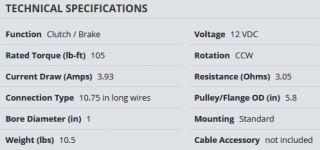
Oh I believe you did Star. I'm curious based on what you've seen in your shop, if you see that as the exception more than the rule. IOW, do you see many low (3A) alternator systems on machines with PTOs? That PTO is spec'd at 3 ohms which means it's pulling 4 amps@12v(fuel solenoid is a fraction of that). That is at the high end of the alternator's capability. Amazing that that machine can charge the battery and power the PTO effectively at the same time (that pesky Kirchoff's current law) but it does! I believe it's because it charges the battery during the peak of the half cycle where the alternator is supplying both charging current INTO the battery and current OUT to the PTO and the moment the voltage drops back down to a certain point close to the battery voltage, the battery current reverses and it outputs current to the PTO. So the stator and diode are not continuously supplying 4amps and you can push the limits. I would appreciate a design with a little more headroom! <since I've gotten flamed for this before, I'm talking conventional current flow!>

FWIW....
 

Richard Milhous

Well-Known Member
Joined
Aug 2, 2021
Threads
6
Messages
173
Also for those that mentioned it, NEVER place diodes in parallel unless a series dropping resistor is used in series with each diode. (This is because the voltage drop across a conducting silicon diode is approximately 0.6 volts and rarely are two diodes exactly the same. The one with the higher drop will 'fight' the other one, kind of like connecting two batteries with different voltages in parallel)

Ruh Roh. I am planning to do that on a trailer brake controller powered by the brake light circuit. I realized I needed a bypass (don't want to lose the brakes if the brakelight switch fails) and that if the brake lights had a short it would just blow the fuse on the bypass and... oops. I figured to isolate the circuits with two diodes in parallel for redundancy because I also don't want even a momentary unexpected brake fail if a diode gives up.

Would it work to match the diodes by their voltage drop at a known current?
 

GoHardrGoHome

Member
Joined
Apr 26, 2019
Threads
2
Messages
21
Slomo, I've tried to identify the stator I have from the B&S Alternator Specifications sheet. I know it only has one wire, but to positively identify it from the B&S sheet is a bit confusing! Even the dealer wasn't positive.
Richard,... as I stated earlier, this engine is in a Grasshopper zero turn mower. Grasshopper doesn't have a very good wiring diagram for the electrical system. It does however show a single wire coming from the stator, going to a diode and then directly back to a fuse panel that is connected to the battery. It does not show any other regulating device in the diagram.
Telesis, thanks for your input. It likely annoys you to read how DIYer's like myself are trying to fix something they know little about, but I've already had the unit to a shop and spent money on labor and "experimental parts" that they recommended!
Telesis, I will take your advise and order the regulator/rectifier and post back with the results.
Glad to see that my posts have intrigued everyone to contribute. I really do appreciate your input.


StarTech

Lawn Royalty
Top Poster Of Month
Joined
Feb 19, 2020
Threads
93
Messages
11,611
Oh I believe you did Star. I'm curious based on what you've seen in your shop, if you see that as the exception more than the rule. IOW, do you see many low (3A) alternator systems on machines with PTOs? That PTO is spec'd at 3 ohms which means it's pulling 4 amps@12v(fuel solenoid is a fraction of that). That is at the high end of the alternator's capability. Amazing that that machine can charge the battery and power the PTO effectively at the same time (that pesky Kirchoff's current law) but it does! I believe it's because it charges the battery during the peak of the half cycle where the alternator is supplying both charging current INTO the battery and current OUT to the PTO and the moment the voltage drops back down to a certain point close to the battery voltage, the battery current reverses and it outputs current to the PTO. So the stator and diode are not continuously supplying 4amps and you can push the limits. I would appreciate a design with a little more headroom! <since I've gotten flamed for this before, I'm talking conventional current flow!>

FWIW....
You and me both as I like at least a 50% surplus but that is what Ariens supplied with that mower. So it is possible but not recommended. Most PTO systems I see usually have at least a 10 amp rated stator.

But some reason the Warner actually pulls less than the spec'd amount and had a resistance closer to 4 ohms.

As for PTO operation I believe they using the battery on valleys and letting stator recharge on the peaks pulses. It seems to work fine as the average DC current is with specs of the stator. With 1800 pulses per minutes (30 per sec) the magnetic field doesn't seen to drop out too much as it take less hold the clutch engaged once it engaged much like a relay can have less holding current and still stay pulled in.

1631994936686.png
 

Telesis

Well-Known Member
Joined
Apr 19, 2017
Threads
2
Messages
151
GoHard, what color is the wire from the stator? If it is a 3A DC system then the wire color would be red(usually) and the original wire would have had the diode in line right at the connector and the connector itself would(usually) be red. If it's one of the higher current output stators(5A, 9A, TriCircuit) then (usually) the wire from the stator is black with a green connector. I realize given the age of your machine that the original connector may be long gone!

Finally, when you replaced the diode due to damage(from your first post), did you identify and repair the cause of the original damage? Diodes rarely fail on their own. Typical failure mode is short or open due to overcurrent.

Let us know!
 

GoHardrGoHome

Member
Joined
Apr 26, 2019
Threads
2
Messages
21
The wire from the stator is black and used to have a green connector. When I originally said it was "damaged", I didn't elaborate on the whole story....the damn connector kept coming apart for me so I decided to fix it. I cut out the old one and soldered in a new connector not realizing that I threw away a diode! The loose connector problem only escalated when I decided to fix it!
The second diode was installed by a local shop that was supposed to have more knowledge on this than I have:rolleyes:
I've got a regulator rectifier on order.
 

VRR.DYNDNS>BIZ

Well-Known Member
Joined
Jul 17, 2016
Threads
1
Messages
213
Agreed! I think I may have already fried a cell in my battery!
No, The opposite. The Battery is frying the system. Batteries can have an intermittent internal single cell short. Additionally, the fuse might be over rated. The output is protected by a fuse that will protect the diode. The only other option is a short on the way to the fuse. An ac pressure on the battery does it good, not harm as it vibrates ions loose to improve battery condition as long as the reverse polarity due to a shorted diode, rather than an open diode, and the fuse protect the system from high current. This sometimes will cause the fuse to repeatedly fail, then people put in a higher fuse. The current output of the charging stator has a rating, and fuse should protect for that level if I were designing it, however, the parts list will usually tell the appropriate size. Replace your battery, replace the diode wire, insure the fuse is good, check the wires for shorts, and go mow.
 

GoHardrGoHome

Member
Joined
Apr 26, 2019
Threads
2
Messages
21
No, The opposite. The Battery is frying the system. Batteries can have an intermittent internal single cell short. Additionally, the fuse might be over rated. The output is protected by a fuse that will protect the diode. The only other option is a short on the way to the fuse. An ac pressure on the battery does it good, not harm as it vibrates ions loose to improve battery condition as long as the reverse polarity due to a shorted diode, rather than an open diode, and the fuse protect the system from high current. This sometimes will cause the fuse to repeatedly fail, then people put in a higher fuse. The current output of the charging stator has a rating, and fuse should protect for that level if I were designing it, however, the parts list will usually tell the appropriate size. Replace your battery, replace the diode wire, insure the fuse is good, check the wires for shorts, and go mow.
The correct fuse is in place. The diode has been replaced twice. The battery was replaced this spring. I'm mowing but the charging system is not operating the way it was designed.
 
Top