Walk behind unit electrical problem

NorthBama

Well-Known Member
Joined
May 28, 2014
Threads
9
Messages
936
Thank you for this information.
I do understand what NO, NC and COM means.
Have looked on YouTube to get a background on how this switch functions on a lawn mower that uses it.

I can tell by your reply that your are capable of checking this PTO switch so i wish you good results on this endeavor. Glad to hear you are helping a friend.
YouTube is my friend also
 

Richie F

Well-Known Member
Joined
Aug 8, 2019
Threads
25
Messages
299
I can tell by your reply that your are capable of checking this PTO switch so i wish you good results on this endeavor. Glad to hear you are helping a friend.
YouTube is my friend also

All I can say is thank you.
 

bertsmobile1

Lawn Royalty
Joined
Nov 29, 2014
Threads
65
Messages
24,995
Bert have you not read my first post ?
I have the wiring schematic already.
What I was hoping for when I started this thread was someone who had this problem and would have told me.
Could have saved a few steps.
You keep talking to me like I'm an idiot.
No, I have not bought a highlighter marker yet to backtrack the circuit. Forgive me your lordship.
I don't need "Join the pink wire to the green wire and cut the blue one just past the yellow wire junction"
When I find the functions of the safety switches it will be very easy to trace the circuits.
I will have time today to compare the problem machine to my friends other 3 SCAG walk behind units.
There are one other 36" and two 48".
Thanks for your input.

Yes I read your first post, several times
And I do appreciate that many people struggle with reading circuit diagrams.
The diagram that you put a link to in your post #18 yesterday shows THE WIRING HARNESS NOT THE CIRCUITS
When I actually checked that link I understood why you were struggling to work out the mowers wiring so I posted a link to a CIRCUIT DIAGRAM which is a totally different animal
Since then I found the rest of the diagram as the link I posted yesterday only had the engine plug to handlebar section on it.
It appears that Scag publish it in 3 different ways, engine side, handle bar side and full diagram, however the full diagram does not show the diode.
But the diode will have less than nothing to do with grounding the magneto so has less than no impact on the no spark problem, being that is is on a power wire and all magneto wires are ground wires.
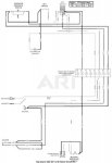
So here is the full wiring diagram, it was there all along I just had not gone deep enough into the parts breakdown to find it the first time , lazy me.
Untitled 11.jpg
When you said you had a wiring diagram this is what I assumed you were looking at.
As you were not then what I posted would have been confusing .
All of the switches in this diagram are shown in the OFF position , ie key off, no operator ( assume this is a bail handle of some sort ) and blades off .
Now the diagram is bad as the white wire which is shown as a double thin black line did not copy properly so lumps of it are missing but the important bit, which plugs & what terminals is shown so if it is confusing, just print it out & join the wires together.
And with this I am out of here.
Note the pins on the PTO switch are numbered in the diagram ( look hard ) but not all PTO switches have the pins numbers on them.
 

Richie F

Well-Known Member
Joined
Aug 8, 2019
Threads
25
Messages
299
Thank you for the schematic.
The one I posted from Parts Tree was the same one from the Scag Parts/Maintenance manual.
I couldn't post the one from the manual because it was in PDF format.
The bottom of the new schematic at the very bottom shows the diode.
https://learn.sparkfun.com/tutorials/polarity/diode-and-led-polarity

Had time to test things yesterday also.
All three switches are NO.They are the key, operator present switch and trans neutral interlock (in neutral).
Also there is a safety in the plug connector for the operator switch. It's a spring loaded button in the middle of the two spade terminals.
When it's pressed in the wires are NO.
Both sets of terminals on the PTO switch in the off position are NC.

I hooked up all safety's and installed my VOM on the wire to the Mag wire unplugged from the engine and the other to engine ground. Used the continuity setting on the meter.
When I engage the PTO I had a ground to engine block. Showing engine will shut off.

Installed a different correct known good PTO switch from another machine and the outcome was the same.

Unplugged the connector to the clutch and had same results.

Unplugged the rectifier wire, tested the engine running and same thing.

I thought maybe the rectifier windings might have been shorted to ground.

Running out of ideas.
 

Richie F

Well-Known Member
Joined
Aug 8, 2019
Threads
25
Messages
299
OK
Thought about this.
Going to have to test every wire in each harness to see if there is a possible short to ground from one of them.
Both harnesses don't show any damage though.
As The Terminator said "I'll be back !"
 

NorthBama

Well-Known Member
Joined
May 28, 2014
Threads
9
Messages
936
rectifier wire?
are you talking about the stater coil winding under the flywheel?
 

Richie F

Well-Known Member
Joined
Aug 8, 2019
Threads
25
Messages
299
rectifier wire?
are you talking about the stater coil winding under the flywheel?

Yes.
There are two, one comes from the ignition coil and the other from the stator winding.
Stator is inside the flywheel.
Coil is on the outside of the flywheel.
 

bertsmobile1

Lawn Royalty
Joined
Nov 29, 2014
Threads
65
Messages
24,995
Thank you for the schematic.
The one I posted from Parts Tree was the same one from the Scag Parts/Maintenance manual.
I couldn't post the one from the manual because it was in PDF format.

PDF's get posted as an attachment so they show up as a link to a downlodd URL just like to one you posted here to the electronics how to page


All three switches are NO.They are the key, operator present switch and trans neutral interlock (in neutral).

No they are not.
The key switch, in the OFF ( NORMAL ) POSITION is closed to ground the coil & kill the spark.
The operator switch is also CLOSED IN THE OFF position so it is a NC switch as well


Both sets of terminals on the PTO switch in the off position are NC.

NO again.
The PTO switch is neither NO nor NC the PTO switch moves continuity from the outside terminal to an inside terminal or visa versa.
In the top right hand corner of the diagram I posted a link to was the connections for the PTO switch which as shown in the diagram moves to connections from left to right ( as drawn ) when off to left to centre when on.

I hooked up all safety's and installed my VOM on the wire to the Mag wire unplugged from the engine and the other to engine ground. Used the continuity setting on the meter.
When I engage the PTO I had a ground to engine block. Showing engine will shut off.

Installed a different correct known good PTO switch from another machine and the outcome was the same.

Unplugged the connector to the clutch and had same results.

Unplugged the rectifier wire, tested the engine running and same thing.

I thought maybe the rectifier windings might have been shorted to ground.

Running out of ideas.

Sit down and trace out the circuits, you are not understanding how they work.
In the off position the magneto is grounded by the key switch.
In the on position the magneto is grounded by the operator switch
 

Richie F

Well-Known Member
Joined
Aug 8, 2019
Threads
25
Messages
299
Sit down and trace out the circuits, you are not understanding how they work.
In the off position the magneto is grounded by the key switch.
In the on position the magneto is grounded by the operator switch

OK will look into this.
Have printed out the schematic you posted also and will study it this morning.
 

Telesis

Well-Known Member
Joined
Apr 19, 2017
Threads
2
Messages
151
The purpose of this message is to (hopefully) provide some clarification with respect to the comments about diodes, rectifiers, AC and DC. You noted correctly before that the voltage coming from the stator of the engine is AC. Some stator assemblies incorporate a single diode in the harness to provide 'half-wave rectified' AC to the rest of the machine. Some older engines incorporate two individually replaceable diodes to do 'full-wave rectification' of the AC to the rest of the machine. Some embed two in a harness. I'm pretty sure that your Scag's Kawasaki engine uses a 3 terminal 'voltage regulator' to convert the AC stator voltage to the DC used by the machine. AC from the stator goes 'into' the regulator on the two terminals labeled AC, and the rectified or DC output comes from the terminal labeled B+, and ground. I'm pretty sure the wire labeled 'rectifier' on the diagram goes to that B+ terminal of the voltage regulator on the engine.

So, what's the purpose of the diode located across the PTO coil? Well it's merely there to provide protection to the regulator located on the engine. It has absolutely nothing to do with converting AC to DC for operating the PTO. It's called a 'flyback' diode. Why is it needed? Whenever a DC current is flowing through a coil, and it is interrupted by the opening of the PTO switch, it creates a huge voltage spike across the coil. I won't bore you with the engineering reason why. That voltage spike can damage the regulator on the engine because it 'sees' or is exposed to the spike. The semiconductor devices embedded in the voltage regulator can be damaged by this kind of high voltage spike. The diode across the PTO coil absorbs the spike by providing an electrical path around the coil, and the regulator on the engine never 'sees' the spike. The fact of the matter is that it is NOT required to operate the PTO. You can disconnect it and operate the PTO just fine. The chance you take is you damage the regulator when you open the PTO. Many machines don't use a flyback protection diode, particularly ones that have batteries. A battery also absorbs that spike. Under normal operating conditions(PTO on), the voltage present on the cathode side of the diode is always positive with respect to the anode and as a result, there is NO current flowing through the diode. That's why it's not necessary for the operation of the PTO. It's for protection only.

I know you said you checked the diode, but understand if this diode were shorted, it could produce the condition you are seeing. I'd still suggest the following quick test. Disconnect one leg of the diode and then start it. Hit the PTO and see if it still kills it. BTW, the chances of this one test causing damage to the engine voltage regulator are very small. That device is robust and it's the repeated exposure to voltage spikes that causes semiconductor breakdown leading to part failure.

FWIW... Let us know how you make out!
 
Top