Safety-switch-related, no-starting problem?

Alex Ethridge

Active Member
Joined
May 25, 2019
Threads
17
Messages
73
I want to thank everyone here for their help as it has validated my belief that this intermittent problem is related to the safety switches. I think maybe I'll order safety switches one at a time and replace them one at a time until I hit on the one that fixes the problem. Diagnosing them by shunting is going to be a problem for me as I don't know whether switches are normally open or normally closed. AND some of these switches have four terminals which further confuses things for me.

Until I hit on the solution, I do have a back-door way of starting it.

Superfluous and useless information: My dad, long gone now, was a master electrician and could make sense of every schematic I ever brought to him. He was a troubleshooter at a heavy industrial manufacturing plant with punches, shears and presses as big as a house. I don't know how many times since he's gone that I have wished I could ask him a question. But thanks to his influence, at least I can wire a house and troupleshoot any appliance I and my family have ever owned.
 

StarTech

Lawn Royalty
Top Poster Of Month
Joined
Feb 19, 2020
Threads
91
Messages
11,476
AFAIK there are no Husqvarna service manuals available in any form at any level for their mowers .
Wiring diagrams are usually at the start of the parts books or end of the owners instruction books .
The top one Star posted is on the last page of your owners manual and is actually the schmetic (schematic) that would be used by the loom maker not a service tech.
The lower one I would like to know where Star got it from as the top one is near useless .
I was researching the owners manuals using the layman's model number RZ3016 then I switched over to using the actual model number along with the revision level through Husqvarna when I came across the owners manual with the good schematics. It was actually on page 28 of 36 of the owners manual.

As I said several of the RZ3016 owners manuals had the first diagram in them. I provide it as just show how stupid the OEM owners manual were for some revisions.
 

Alex Ethridge

Active Member
Joined
May 25, 2019
Threads
17
Messages
73
I want to thank everyone here for their help as it has validated my belief that this intermittent problem is related to the safety switches. I think maybe I'll order safety switches one at a time and replace them one at a time until I hit on the one that fixes the problem. Diagnosing them by shunting is going to be a problem for me as I don't know whether switches are normally open or normally closed. AND some of these switches have four terminals which further confuses things for me.

Superfluous and useless information: My dad, long gone now, was a master electrician and could make sense of every schematic I ever brought to him. He was a troubleshooter at a heavy industrial manufacturing plant with punches, shears and presses as big as a house. I don't know how many times since he's gone that I have wished I could ask him a question. But thanks to his influence, at least I can wire a house and troupleshoot any appliance I and my family have ever owned.

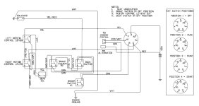
I was researching the owners manuals using the layman's model number RZ3016 then I switched over to using the actual model number along with the revision level through Husqvarna when I came across the owners manual with the good schematics. It was actually on page 28 of 36 of the owners manual.

As I said several of the RZ3016 owners manuals had the first diagram in them. I provide it as just show how stupid the OEM owners manual were for some revisions.
That's how I looked up the manual I have been using, by actual model number. It has a schematic I can read on page 46 of 56.Husqvarna RZ3016 Schematic.jpg
 

StarTech

Lawn Royalty
Top Poster Of Month
Joined
Feb 19, 2020
Threads
91
Messages
11,476
I want to thank everyone here for their help as it has validated my belief that this intermittent problem is related to the safety switches. I think maybe I'll order safety switches one at a time and replace them one at a time until I hit on the one that fixes the problem. Diagnosing them by shunting is going to be a problem for me as I don't know whether switches are normally open or normally closed. AND some of these switches have four terminals which further confuses things for me.

Until I hit on the solution, I do have a back-door way of starting it.

Superfluous and useless information: My dad, long gone now, was a master electrician and could make sense of every schematic I ever brought to him. He was a troubleshooter at a heavy industrial manufacturing plant with punches, shears and presses as big as a house. I don't know how many times since he's gone that I have wished I could ask him a question. But thanks to his influence, at least I can wire a house and troupleshoot (troubleshoot) any appliance I and my family have ever owned.
Well the two pole switches in the diagram contains one pole normally closed and the other pole normally open (referencing switch non depressed rest position). On the switch terminal themselves the normal closed pole will be labelled NC (for normally closed).

Now on the schematic the motion control arms are in neutral (outboard position) which means the switches are depressed (opposite of the switch rest position). The brake and PTO (deck switch) are shown the the rest position (ie not depressed).

If you are going to use plug and play I would suggest first replacing both of the motion control arms switches as they are the ones that tend to go out the most as they receive the most wear.
 

Alex Ethridge

Active Member
Joined
May 25, 2019
Threads
17
Messages
73
Yes, I've ordered one of those for diagnostic. There are (according to the parts manual) four of that switch on the mower; however, the way the schematic is drawn, it looks like there are five but one of them must be a different part number. Anyway, I'll check the ignition switch tomorrow and if that isn't it, I'll wait on the control arm switch to get here and substitute those one at a time.
 

StarTech

Lawn Royalty
Top Poster Of Month
Joined
Feb 19, 2020
Threads
91
Messages
11,476
Yes the deck switch is a snap-in design where the other four are bolt (screw) and nut mounted.

And as I said on the control arm switches I would replace both at the same as they are equally worn. And if anything like the ones I deal with replacing one usual means the mower will back in short order for the other to be replaced. I deal with cub Cadet ZTR where they disengage the PTO electric PTO clutch in full reverse so their contacts get burned from constant diesengaging and re-engaging the clutch.

But of course in shop setting it saves time when I do both as if I don't it means I have to get the tools, parts out, and do paperwork a second time. Considering as busy as the one person shop is I don't have time to waste.
 

bertsmobile1

Lawn Royalty
Joined
Nov 29, 2014
Threads
65
Messages
24,995
THe cranking circuit is a daisy chain so power has to pass through all of them
Thus they are usually NO switches which is why I suggested to jump the plugs an still suggest to do that as some of these switches can only be replaced after all of the body work is removed
All of the safety switches are the same construction.
The external terminals extend into the body and the plunger has a strip of copper which will either make or break connections .
Thus they all connect FLAT to FLAT on the plug which should be obvious because of the colour coding
In your case they will all be yellow either solid or with a trace ,
A common practice is to change the trace between switches because it makes construction of the loom easier .
 
Top