Use this procedure along with IlEngines instructions and you should be able to track down the problem. As for a multimeter, I would suggest the best one you can afford.
Electrical* problems can be very easy or very difficult, depending on four things.
1. * How well you understand basic electricity.
2. *What tools you have and know how to use.
3. *How well you follow directions.
4. *You don't overlook or assume anything and verify everything.
Remember we cannot see what you are doing. *You are our eyes, ears and fingers in solving this problem. *You must be as accurate as you can when you report back. *The two basic tools we will ask you to use are a test light and a multi-meter. *If you have an assistant when going through these tests it would be very helpful. *These steps work the best when done in order, so please don't jump around. *Now let's solve this problem.
First, check the fuse(s), check battery connections for corrosion (clean if necessary) and *voltage - above 12.5 volts should be good.*
Second, check for power from the battery to one of the large terminals on the solenoid. *One of the wires is connected directly to the battery and has power all the time so one of the large terminals should light a test light or show 12 volts on a meter at all times.*
Third, *check for power at the small terminal of the solenoid while depressing the clutch/brake pedal and holding the key in the start position (you may need an assistant to sit in the seat to override the safety switch). If your solenoid is a four wire solenoid, check both small wire terminals as one is ground and the other is power from the ignition switch. *If your solenoid is a three wire solenoid, make sure the solenoid body is not corroded where it bolts to the chassis of the mower as this is your ground path back to the battery. *If in doubt, remove the solenoid and clean the mounting area down to bare metal. *If there is no power to the small terminal then your problem is most likely a safety switch, ignition switch or in the wiring.*
Fourth, check for power on the other large terminal of the solenoid while holding the key in the start position (you may need an assistant to sit in the seat to override the safety switch). *If you have power what is the voltage?
Fifth, check for power at the starter while holding the key in the start position (assistant again). *If you have power what is the voltage?
Sixth, check your ground circuit back to the battery.
After you have gone through each of the above steps, let us know what happened when you did each step. *At that point we will have great info to tell you how to proceed. *Remember you are our eyes, ears, and fingers, so please be as accurate as possible.
Be as specific as possible with voltage readings as this will help diagnose your problem quicker. *If you do not know how to perform the above checks, just ask and I will try to guide you through it. *Youtube also has some videos and as you know a picture is worth a thousand words.
I will do my best to answer your questions in the order you have raised them.
First, I have checked all three of the fuses that are shown on my wiring diagram. One is connected to the red wire to the starter and the other two are part of a harness near the key switch. All three fuses are good and intact. I am unaware of any other fuses; if there are any other fuses, please advise. Battery connections are clean. Voltage across the battery is 14v.
Second, there are 14v from the battery to the large terminal to the solenoid.
Third, there is no power at the small terminal of the solenoid with the key in the start position. Solenoid connections are clean.
Fourth, there is no power the the other large terminal on the solenoid while holding the key in the start position
Fifth, there is no power at the starter while holding the key in the start position.
Sixth, battery ground circuit is good.
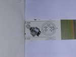
Also, I have tried to test the key switch. I did not find a good wiring diagram of the key switch itself in the operator's manual, so the information I have based my testing on was obtained on line from other sources. I will describe and if I am in error please point it out and direct me otherwise. My key switch has 6 terminals. A single yellow wire is connected to one of the spade terminals. A plug is connected to the remaining 5 spade terminals. With the key in the off position, I have continuity between the G and M terminals. With the key in the lights position, I have continuity between the B and L terminals. With the key in the run position, I have continuity between the B and S terminals. I am not sure what the yellow wire is and did not include it in any of my switch testing. Should I have? If this switch testing was in error, please advise.
Also, I was unable to demonstrate continuity between the green wire at the the key switch and the green wire at the starter solenoid.
Lastly, I have tested all the safety switches I know how to test, namely the right and left handle neutral switches, the seat switch, and the brake interlock switch. I am unsure as to how to test the PTO switch, but I have a second mower and I have examined its PTO switch and the continuity pattern seems to be similar. However, I would appreciate more specific instructions as to how to accurately test it.
The green solenoid wire coming off the key switch connects to a relay and then appears to go to a module plug. Can anyone give me instructions on how to test either of these? As a last resort, I can take the relay out of my other mower and put in the bad one and see if it works, but there should be a way to outright test it.
Again, thanks to all who have contributed on this thread. I think I'm getting there and I've learned a lot along the way, and when it's not frustrating, it's fun.