You are using an out of date browser. It may not display this or other websites correctly.
You should upgrade or use an alternative browser.
You should upgrade or use an alternative browser.
More options
Export threadMcTurff
Active Member
- Joined
- Jul 12, 2025
- Threads
- 5
- Messages
- 62
Just found this video
End of video this guy shows camshaft side of engine and tab looks just like mine same orientation!
Now im confused
Looks like you have the shaft/lever turned the right way Notice the little shiny spot on the lever that is where the thimble is contacting the lever. While it is apart spin the governor and see if the flyweights and thimble move properly. As you are reinstalling the pan check to be sure the governor is engaging the cam, a small wire or thin flat plate can go between the housings. One more question does the governor shaft appear installed correctly? Can the thimble fully retract into the weights? If so the only thing left is the external adustment.
McTurff
Active Member
- Joined
- Jul 12, 2025
- Threads
- 5
- Messages
- 62
Yes shaft looks good and thimble and weights spin free !Looks like you have the shaft/lever turned the right way Notice the little shiny spot on the lever that is where the thimble is contacting the lever. While it is apart spin the governor and see if the flyweights and thimble move properly. As you are reinstalling the pan check to be sure the governor is engaging the cam, a small wire or thin flat plate can go between the housings. One more question does the governor shaft appear installed correctly? Can the thimble fully retract into the weights? If so the only thing left is the external adustment.
Not sure what you mean by the thin wire?
To probe or feel for gears properly meshing between cam and governor gear!
Anyway again thanks to your help and explanation I think im in the right track
Hopefully it works this time around!!
By a thin wire I just meant something that would go between the block and sump to be sure the governor is engaging the cam.
Somewhere you've got to win!! Just trying to share what I have learned over the years, as I know governor are a a mystery to most people.
Somewhere you've got to win!! Just trying to share what I have learned over the years, as I know governor are a a mystery to most people.
McTurff
Active Member
- Joined
- Jul 12, 2025
- Threads
- 5
- Messages
- 62
Yes I understood after reading againBy a thin wire I just meant something that would go between the block and sump to be sure the governor is engaging the cam.
Somewhere you've got to win!! Just trying to share what I have learned over the years, as I know governor are a a mystery to most people.
Anyway
Got it back together same thing!!
Adjusted governor
Running wild i videoed my whole reinstall hoping it could help someone and maybe it still will
How to or not how to video but I can't see how it could be done any other way!
I don't know what else to do!
Everything lined up perfect not hard to see
I may make the video available it came out good maybe someone can see something i did wrong not afraid of criticism but I just can't see any other way to do it!
I seem to always get head scratcher projects!!
McTurff
Active Member
- Joined
- Jul 12, 2025
- Threads
- 5
- Messages
- 62
Here is my video I feel kinda defeated but maybe still be some good info for someone!By a thin wire I just meant something that would go between the block and sump to be sure the governor is engaging the cam.
Somewhere you've got to win!! Just trying to share what I have learned over the years, as I know governor are a a mystery to most people.
At least it shows some detail of this engine opened that i haven't seen!
Now have to figure what to do next!
By the video you have everthing correct on the inside.
Not that you do not know what youi are doing, you seem quite knowlegable. But I question the external adjustment. I you turn the shaft correctly remember you are moving the lever against the thimble, so when the engine starts the weights fly out, push the thimble up moving the lever turning the shaft and closing the carburetor plate. By the video you would turn the shaft anti-clockwise until it stops (touches the thimble) with the throttle wide open, tighten bolt and all should be well. If adjusted the wrong way the governor arm will not move.
Here s the procedure from Breaks & Scapem.
Hope all works out and you are back in the saddle and don't need to continue getting frustrated at this issue.
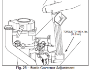
STATIC GOVERNOR ADJUSTMENT
1. With governor lever nut loose, push governor lever
counter-clockwise as far as it will go (wide open
throttle) and hold in this position.
2. Rotate governor shaft counter-clockwise as far it
will go, Fig. 25.
Torque governor nut to 100 in. lbs. (11.0 Nm). A 7/16”
crowfoot socket may be required on ducted engines.
See procedure below for dual speed or 1800 RPM
generators. Fig. 25 – Static Governor Adjustment


McTurff
Active Member
- Joined
- Jul 12, 2025
- Threads
- 5
- Messages
- 62
I have adjusted it so many times each way. That it's driving me crazy. There's no way that I could have got it wrong after doing it. So many times testing it each time, it's very frustrating, but I just don't think it's working right!!By the video you have everthing correct on the inside.
Not that you do not know what youi are doing, you seem quite knowlegable. But I question the external adjustment. I you turn the shaft correctly remember you are moving the lever against the thimble, so when the engine starts the weights fly out, push the thimble up moving the lever turning the shaft and closing the carburetor plate. By the video you would turn the shaft anti-clockwise until it stops (touches the thimble) with the throttle wide open, tighten bolt and all should be well. If adjusted the wrong way the governor arm will not move.
Here s the procedure from Breaks & Scapem.
Hope all works out and you are back in the saddle and don't need to continue getting frustrated at this issue.
STATIC GOVERNOR ADJUSTMENT
1. With governor lever nut loose, push governor lever
counter-clockwise as far as it will go (wide open
throttle) and hold in this position.
2. Rotate governor shaft counter-clockwise as far it
will go, Fig. 25.
Torque governor nut to 100 in. lbs. (11.0 Nm). A 7/16”
crowfoot socket may be required on ducted engines.
See procedure below for dual speed or 1800 RPM
generators. Fig. 25 – Static Governor Adjustment
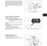
View attachment 71430
View attachment 71431
All I can do is keep trying
And my knowledge comes from just tinkering, sometimes you get lucky, but most of my info has come from people like you.So I thank you for that!!
Couple questions:
Can you hold the carb linkage at idle and get a slow idle? (I'm talking about holding the carb shaft against the idle set screw)
Next: You mention that yours runs at high rpm even with the dash control set at slow. If so you have a throttle plate control problem instead of a governor problem.
In post #31 and 33 I posted that I my opposed twins will slow idle with the dash control set at slow and the governor not even needed. The governor arm is actually locked out mechanically and not even used at slow idle on mine,(cannot even move the governor arm with hand because it's locked mechanically at low idle) but does have a governored idle part way up on the dash throttle.
My engine model types and codes are as follows 422707 1263 01, code 9403105A and 42E707 2631 E1 code 9811235B and both use the same governor arm and throttle plate and springs.
Your engine shows on parts lists that it uses the same governor arm and throttle plate as my engines. (but Briggs does have other type throttle plates and governor arms for the opposed twins and they must be kept matched for correct mechanical governor/throttle operation)
Post up some good pictures of your governor arm and throttle plate. I see that Briggs has different type throttle plates and governor arms for the opposed twins is why I ask about pictures of yours.
Also post up close up pictures of yours throttle plate when at idle and also a full throttle.
