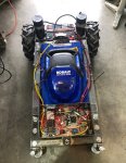
I'm building a RC mower ( https://www.lawnmowerforum.com/show...rt-but-not-self-propelled?p=336699#post336699 ).
Decided to go with a 20" 40V Brushless as they were on sale and it has the one lever deck height adjustment which I am hoping to utilize with an actuator for remote control of cutting height. But we will see.
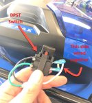
Anyways, does anyone have a wiring diagram for this model? There is a DPST switch with one side wired together, which seems odd. I removed the mechanical safety as I will be using a 10 Amp RC relay to replace the switch. Just seems odd why it would be wired this way. In the pics below, if you bridged the black and green wires it seems you'd have the exact same circuit and could use a SPST switch...so why is it wired this way? Any ideas?
Not sure yet which lead goes to battery +, but will post more once I get deeper into tear down so I can make the welded frame for drive motors, drive batteries, electronics, etc.
Any help appreciated....


