troy bilt Bronco wiring diagram

thanks. I don't have the old stator. You are right the new engine has a rectifier/regulator. IT sure appears the only AC wire from the Stator goes right into the rectifier. No other wire but ground. So all power is DC? right?

I was now able to read the diagram. It seems a little different than my Bronco's actual wiring in that the blue alternator wiring on the 6 pin connector is an orange wire that I am told is used for an accessory. The lighting wires are actually blue and green as the diagram shows. Some how the orange wire connects with the Blue lights wire. The Orange wire is getting power from both the rectifier and from the battery. When I disconnected them the lights went out permenantly and tractor had running issues.

I do not know enough to modify the wiring to get the lights to only come on when the engine is running. My simple thinking is to put a toggle switch on the lights green ground wire to control the lighting. Not ideal, but it is all I know enough to do.

Small Engine Warehouse provided me with this general guidance attached.

Am I missing an easy way to modify something so the light will only work while the engine is on?
Sound the current engine has a Tri-Circuit stator. Either on the mower side or the engine side there is jumper to what was AC side of a Dual Circuit stator.

There is two options. One of which you already thought of. The other is change how the wiring harness circuit is connected. Current the charge wire is probably connected at the starter solenoid. It need to be rerouted to the ignition switch A terminal so when off it disconnects that circuit. With this the lights would come on when the switch is in any position other than off. It also stop the regulator from draining the battery during long storage times.
 
Hello N.,

It is common for wire colors to change from the engine harness to the chassis harness. This creates confusion unless you have adapted a few engine swaps in the past.

Sometimes these engine swaps don't come easy and minor modifications have to be made. Installing a simple 2-pin weatherproof toggle switch for the headlights would work. Just "T" into the small battery charge wire to feed power to the headlamp switch, then attach the blue headlight wire to the other terminal of the switch. I advise you to put an inline fuse holder & fuse in the headlight circuit near the switch to avoid any future issues if a headlight wire gets grounded or pinched. This way you can control the headlights on/off with the engine running or not running.

My blind guess:

The new engine has 2 wires coming from the stator under the flywheel to the voltage regulator. The regulator is attached to the engine and grounded internally through the metal housing. The regulator has a 2-wire connector that attaches to the stator plug and the lone red-wire is the 12V DC charge wire that goes to the battery.

Is this close to what you have?

A couple of pictures of the regulator wiring would be ideal if you can attach them.
 

Attachments

  • IMG_8206.jpeg
    IMG_8206.jpeg
    19.4 KB · Views: 6
  • IMG_8207.jpeg
    IMG_8207.jpeg
    22.4 KB · Views: 6
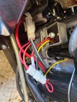
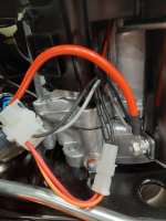
What I have described earlier may have been a confusion. These pics should help clear up the current wiring on the new engine. The yellow wire comes from the stator and goes into the rectifier. A red wire comes out of the rectifier and goes to a connector that connects it to the red and orange wire on the tractors 6 pin connector. I think the orange wire is similar to the blue wire on the wiring diagram. The red wire must ultimately go to the battery for charging but its exact pathway has not been confirmed. The grey wire is for the fuel solenoid and the black goes to ground the magneto. I have never left the battery connected for long so I do not know if there is another drain on it with the engine off. i.e. the rectifier. However I can see how that may be a problem. If that is the case just a simple toggle on the head lights is not enough.

If I put a fuse on the light, what size is reasonable.? 3 or 5 amps? I do not know what wattage the 2 lights consume. I looked at a bulb base and there was no markings. They look like an automotive tail light bulb. I may go to Lowes and look at their current MTD tractors on display and take a pic of their wiring to compare.
 
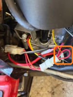
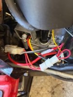
Disconnect the wire loop [orange box] and the lights should be disabled. Then you wire in a switch or tap into wire at the "A" terminal of the ignition switch.

1776461755377.png

The bulbs are 1156 and draw 2.1 amps a piece. IE two draws 4.2 amps so fuse at 5 amps.
 
Disconnect the wire loop [orange box] and the lights should be disabled. Then you wire in a switch or tap into wire at the "A" terminal of the ignition switch.

View attachment 73063

The bulbs are 1156 and draw 2.1 amps a piece. IE two draws 4.2 amps so fuse at 5 amps.
Actually, I would recommend a 7.5-amp fuse. A 5-amp fuse is too close to the total draw of the bulbs, not including heat load after being used for a while.
 
OK thanks to both Auto Doc's and Star Tech. Removing that jumper wire outlined above makes perfect sense to me and that is what I first did. This is what happened.

The lights went off in all cases. Engine on or Engine off. No lights with the key in any position. The engine started and I took the tractor out to test all other functions. All went well until I applied the PTO adding a load to the engine. The Engine started to struggle and buck. It would just die out. I tested this several times and that scenario repeated. I put the jumper wire back on to the orange wire and everything reverted back to its baseline where everything worked as it should but again, the light were always on.

So what is going on? One theory is that power was being stolen from the fuel solenoid hence starving the engine of gas. Does that sound plausible? If not, what was going on?

If I do as advised, won't I get the same problem when I apply the PTO load?
Thoughts on this? Thanks!
FYI
I did go to Lowe's and took a picture of the wiring on a similar C'man tractor. As you guys said it does not have a rectifier and has a duel wire output. The AC goes to the orange wire and the other wire has a diode that feeds the red wire to charge the battery with a pulsed DC. I also looked at a JD tractor with the identical 17.5HP B&S engine. It has the rectifier with the identical wiring coming out of the engine. Including the jumper wire to the orange wire. The light wiring appears to run through a relay under the dash. Many other wires also run through that relay.
 

Attachments

  • 20260417_180048.jpg
    20260417_180048.jpg
    2.1 MB · Views: 0
This rider has a manual lever operated PTO according to the wiring diagram, but it also has a logic board and PTO cutout if the machine is put in reverse. (Child safety option).

If you only mow in daylight hours, disconnect the lights until you figure out the correct way to power them with a separate switch and inline fuse.

Connect the original jumper loop back together on the engine connector.

According to the wiring diagram this mower was originally equipped to run the headlights at all times off of the stator AC output with the engine running. (CANADA and some European countries)

Since you swapped the engine to a different design with a regulator rectifier, the lights require a separate switch to function. This would be the simplest method to make the light work when needed.

The light bulbs themselves operate at such low amperage that they will work with AC or DC current.
 
This rider has a manual lever operated PTO according to the wiring diagram, but it also has a logic board and PTO cutout if the machine is put in reverse. (Child safety option).

If you only mow in daylight hours, disconnect the lights until you figure out the correct way to power them with a separate switch and inline fuse.

Connect the original jumper loop back together on the engine connector.

According to the wiring diagram this mower was originally equipped to run the headlights at all times off of the stator AC output with the engine running. (CANADA and some European countries)

Since you swapped the engine to a different design with a regulator rectifier, the lights require a separate switch to function. This would be the simplest method to make the light work when needed.

The light bulbs themselves operate at such low amperage that they will work with AC or DC current.
OK. So I will put a toggle on the blue wire going to the lights while leaving the red to orange jumper wire in tact. Earlier you thought the regulator may drain the battery some amount in longer storage. Is that common or something that may happen because the re power engine has the rectifier?
 
The blue wire will have to be its own lighting circuit and attached to a direct power such as the start solenoid where the battery cable wire attaches. Then install an inline fuse and a toggle switch.
 
The simplest thing to do is to jumper the blue and white wires together at the engine connector then when the ignition switch is on the lights are on and the switch is off the lights are off.
 
Back
Top