Believe me, you won't be the first guy with $15,000 wrapped up in a motorized item with a Blue Book value of $200 !! ?Ok, somebody’s not trying hard enough to stop me from telling myself “while it’s apart I might as well do that too....”
You are using an out of date browser. It may not display this or other websites correctly.
You should upgrade or use an alternative browser.
You should upgrade or use an alternative browser.
LA150 Oil Sump & Other Adventures
- Thread starter Gumby83
- Start date
More options
Export threadMost of that will be spent adding a sweet stereo system.Believe me, you won't be the first guy with $15,000 wrapped up in a motorized item with a Blue Book value of $200 !! ?
Hammermechanicman
Lawn Addict
- Joined
- Jan 10, 2020
- Threads
- 69
- Messages
- 3,942
Famous words heard at every car dealership
"For just a few dollars we can get you into a ........."
"For just a few dollars we can get you into a ........."
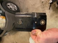
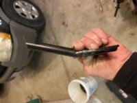
Meant to share these as well. The first 2 are the adjuster bracket post-repair but pre-rattle can. All I did was bend the bracket back to its original shape, then used a cutting wheel to open up the seam (cutting a little deeper than the original crack) and MIG welded it.
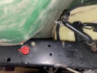
The next was a spur of the moment decision to mount the fuel line shut off in the frame - I’m glad it worked out because I took a SWAG (scientific wild a** guess) at the location - it was pretty close to not being a good one.
I wanted it closer to the tank just so it wouldn’t interfere with the linkages closer to the engine. I used a 3/4” hole saw and mounted it with padded clamps and 1/4” bolts. I’d searched for a metal petcock type valve but didn’t find one that I was confident would work in this location so I settled for the plastic one I already had and may replace it with a metal one in the future.


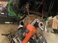
So when I went to install the flywheel, I realized I didn’t have a good way of holding it for torquing. I’d already installed the drive and clutch pulleys so I didn’t want to rely on the bolt for those. I settled on a 2.5” bolt and my 24” pipe wrench - it worked pretty well. The wrench grips the bolt and the socket I had was just a little bit smaller than the flange, so I was able to torque it without interference. Just thought that was a good tip to share.
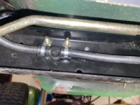
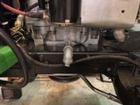
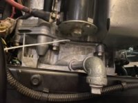
I’d been wanting to add a better drain valve for the oil, but wasn’t able to find anything I was satisfied with, so for now I settled on a 4” galvanized fitting and elbow with plug to at least keep the oil from draining/dripping onto the frame.
And finally, I started on the temp gauge install. I debated with myself for quite a while about whether or not to purchase ready made CHT kit, but it just seemed overpriced for what it was - plus I’d have to buy 2 of them because I couldn’t find anyone offering a kit with 2 probes.
I was finding thermocouples for cheap and the only visible difference between a thermocouple or a CHT thermocouple was the ring lug.
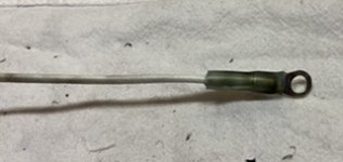
I realized the ring lug on the CHT sensor was basically just a large electrical eyelet with a thermocouple secured to it, so I took a shot at making my own. I couldn’t find any ring lugs large enough to fit around the base of the spark plugs, so I decided to try placing the probes on the bottom heat shield bolt on either head. It’s not be the most accurate place for the measurement, but again, I’m just looking for a baseline temp to use as a reference, so we’ll see how it goes.
I don’t have the gauge/reader installed yet but I readied the probes.
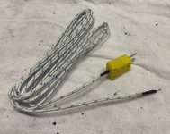
I’m using 2 type K thermocouples wired in parallel. I found a 5 pack on Amazon for about $15 - the plugs on them happen to be the exact same spacing as the terminals on the reader, so I’m gonna drill holes in them to accommodate the screws so I don’t have to try and secure 2 single strands of wire to them.
All I did to make the probe was insert the thermocouple into the eyelet without crimping it, then used the heat shrink to secure it. The eyelet is sandwiched between the head and heat shield with the bolt run through it

I’d been wanting to add a better drain valve for the oil, but wasn’t able to find anything I was satisfied with, so for now I settled on a 4” galvanized fitting and elbow with plug to at least keep the oil from draining/dripping onto the frame.

And finally, I started on the temp gauge install. I debated with myself for quite a while about whether or not to purchase ready made CHT kit, but it just seemed overpriced for what it was - plus I’d have to buy 2 of them because I couldn’t find anyone offering a kit with 2 probes.
I was finding thermocouples for cheap and the only visible difference between a thermocouple or a CHT thermocouple was the ring lug.
I realized the ring lug on the CHT sensor was basically just a large electrical eyelet with a thermocouple secured to it, so I took a shot at making my own. I couldn’t find any ring lugs large enough to fit around the base of the spark plugs, so I decided to try placing the probes on the bottom heat shield bolt on either head. It’s not be the most accurate place for the measurement, but again, I’m just looking for a baseline temp to use as a reference, so we’ll see how it goes.
I don’t have the gauge/reader installed yet but I readied the probes.
I’m using 2 type K thermocouples wired in parallel. I found a 5 pack on Amazon for about $15 - the plugs on them happen to be the exact same spacing as the terminals on the reader, so I’m gonna drill holes in them to accommodate the screws so I don’t have to try and secure 2 single strands of wire to them.

All I did to make the probe was insert the thermocouple into the eyelet without crimping it, then used the heat shrink to secure it. The eyelet is sandwiched between the head and heat shield with the bolt run through it


