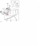
Hello & Thanks Again to All...
I'm still in the dark as to how to get to the Fuel Indicator Pivot so that I can clean it out and let it swing properly and give me a good Fuel Reading.
Thanks !
edv7028
I told you in post # 9
Pull off both rear wheels
The fuel indicator is right there in front of your eyes,
Well in front of my eyes because I put the rear axel on 20" high stands so I can sit on a seat.
Looks like the link to the parts page did not work, however if you type
d140 ( note no spaces) in the little window at the top it will bring up your mower as a clickable link.
Click on the line that looks like this
10445 - D140 100 Series Tractor - 02Nov16 ( FR DE IT ES )
Then click on this
Sectional Index
Then click on this
30 - Fuel And Air
Then click on this
20 - Fuel Tank (100001 - )
Note there are 4 fuel tank diagrams ( 17-18-19-20)
17 is the first type without the idiot fuel level indicator
18-19-20 are the new type
18 & 20 are the same
19, the image Blaz posted is the same tank, but a different image including the California only charcoal filter and showing the fuel indicator as disconnected parts.
IF you bought the digital version of the technical manual which you would have by now , then you could have read the :-
THEORY OF OPERATION
The rear of the fuel tank ( Part 1 ) sits in a channel in the frame which allows it to pivot up and down at the front end.
The front end of the fuel tank sits on the foot of the indicator arm ( part 11 )
The indicator arm itself pivots on the support base ( part 12 )
The front of the fuel tank is held up by a pair of springs ( part 13 ) which span from an anchor point on the fender ( not shown in this diagram ) to bushes ( part 7) over protrusions moulded into the tank and fastened by a spring clip ( part 6).
AS fuel is placed into the tank , the weight of the fuel tank increases causing it to stretch the springs allowing it to depress the arm which being a bell crank causing the visible indicator to rise.
If you use the link to the JD parts diagrams and ferret a bit you might also find section
85 - Mower Deck And Lift Linkage
Clicking on that will reveal subsection
44 - Mower Deck Lift Linkage
PAY ATTENTION THIS IS IMPORTANT
This diagram is wrong it is for the previous model ( first fuel tank diagram 17 ) without the fuel indicator.
The deck lift rod ( part 21 ) is incorrectly named "universal driveshaft".
On the older system it is retained by a pair of steel saddle clamps ( part 15 )
On your mower the deck lift rod is retained by the support base ( part 12 in the previous diagram ) which is plastic.
if the deck is given a hard whack when on a high cut position the lift rod ( part 21 ) hits the plastic support base and it breaks as mentioned way back in a previous post
Grass accumulates between the indicator arm & the support.
It also accumulates under the fuel tank with the same effect.
Don't forget to grease the axle or the wheels will rust solid to the axle.

