Etesia Ride On Mower Electrical Loom Help

kevjns

Member
Joined
Sep 26, 2015
Threads
4
Messages
22
Hi

Just fitted a new wiring loom on my ride on mower as the old one was butchered and dangerous by the previous owner.

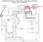
I have 3 wires left were im not sure were they go. according to the mower manual wiring diagram they go to the right front spade terminal on the solenoid but the cable have a spade terminal with a ring hole in it.

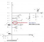
Also I have to diagrams which contradict each other ive attached them to this msg.

Cheers guys
 

Attachments

  • Wiring bahia.jpg
    Wiring bahia.jpg
    133.2 KB · Views: 41
  • Etesia Bahia 2.jpg
    Etesia Bahia 2.jpg
    65.3 KB · Views: 31

bertsmobile1

Lawn Royalty
Joined
Nov 29, 2014
Threads
65
Messages
24,995
They are all earth (-) wires
Looks like they will all join at a mounting bolt for the starter solenoid.
There was probably a spade terminal with a ring on the other end that went under the same bolt.
They are available form most electric copmonant store ( Tesco ? ).

Is the solenoid a 3 pole or 4 pole ?
Hook them up and see if you get a spark and that the solenoid energises.
 

kevjns

Member
Joined
Sep 26, 2015
Threads
4
Messages
22
It's a 4 pole solenoid. I tried it on the empty spade terminal on the solenoid it fired up but then I couldn't turn off the engine via the key ignition. Got off the seat which has a new kill switch still ran. Had to pull the spark plug cap in the end.????
 

bertsmobile1

Lawn Royalty
Joined
Nov 29, 2014
Threads
65
Messages
24,995
In that case they go to earth via the mounting bolt of the solenoid.
 

kevjns

Member
Joined
Sep 26, 2015
Threads
4
Messages
22
Thanks for your help tried your suggestion now when I turn the key I get a click sound. If I turn the blade switch to on and turn key can hear the magnetic clutch moving. If I get of seat or handbrake is off get nothing so safety switches are working to. Added another pic if it helps...strange one this
 

logan01

Well-Known Member
Joined
May 13, 2014
Threads
7
Messages
313
I don't see your third pic.
 

logan01

Well-Known Member
Joined
May 13, 2014
Threads
7
Messages
313
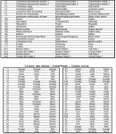
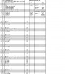
As depicted in the first diagram, one of the black wires originates from item 104 and the other from item KA1? Is it still configured that way? Do you have a key/legend that indicates which component is which, for example KA1. 104, etc? Is #25 the blue wire or an item to where the blue wire goes? Whatever #104 is, make sure that ground wire has a very good ground on each end. Which item is the starter?
 

kevjns

Member
Joined
Sep 26, 2015
Threads
4
Messages
22
As depicted in the first diagram, one of the black wires originates from item 104 and the other from item KA1? Is it still configured that way? Do you have a key/legend that indicates which component is which, for example KA1. 104, etc? Is #25 the blue wire or an item to where the blue wire goes? Whatever #104 is, make sure that ground wire has a very good ground on each end. Which item is the starter?


Lol sorry that would have helped. Ive had to print screen the pdf so I hope there readable. the baiha 1 file is for the first diagram and two others for the second one.

cheers guys :)
 

Attachments

  • baiha 1.jpg
    baiha 1.jpg
    351.9 KB · Views: 13
  • baiha 2.jpg
    baiha 2.jpg
    179.6 KB · Views: 10
  • baiha 2a.jpg
    baiha 2a.jpg
    54.9 KB · Views: 10
Top