Briggs 42A707 Stator output measurement

StarTech

Lawn Royalty
Top Poster Of Month
Joined
Feb 19, 2020
Threads
91
Messages
11,490
Yes Net I agree that it is most likely the diode only is bad as that is what I find most times here; unless, someone reversed the voltage to the stator.. This why I order these diode in quantity of 20 ea at a time and of course the need terminals.
 

bertsmobile1

Lawn Royalty
Joined
Nov 29, 2014
Threads
65
Messages
24,995
Just remember that the single diode is a really cheap method of charging the battery .
Anything that impeeds the battery charging like a bad ground connection will cause a lot more current to be blocked by the diode and drastically shorten it's working like.
Similar with bad plugs, a connection that sparks or a bad battery and in particular continually jump starting rather than replacing a bad battery.
 

StarTech

Lawn Royalty
Top Poster Of Month
Joined
Feb 19, 2020
Threads
91
Messages
11,490
Anything that impeeds the battery charging like a bad ground connection will cause a lot more current to be blocked by the diode and drastically shorten it's working like.
This simply doesn't makes sense as higher the circuit resistance the lower current. Besides I use 1N5408-G diodes which have a 200 amp surge rating; though, I believe Briggs used the 200 PIV version. Just as cheap to use the 1000 PIV version.
 

Bentoolong

Member
Joined
Feb 12, 2021
Threads
2
Messages
19
Well some good news. I got a new starter installed and that made a huge difference. I bench tested both starters prior to the swap and the new one turned much faster.
I also installed a new diode and that solved the charging issue (13.9V at the battery).

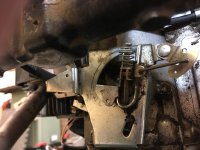
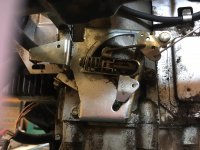
My next question involves the governor. How exactly should this be adjusted? I don't have and issue with anything yet but I haven't done any work with it.
The idle is nice and the part attached the the throttle seems to move through its range rather nicely.
There seems to be a lot of slack in the adjustable screw (with spring). How is that adjusted exactly.
I don't have a reason to believe anything is missing or that it was ever even adjusted. I don't have a tach.
I'm just trying to get things adjusted better and gain some knowledge.
I've looked around at the motor manual (Briggs 42A707) but don't see any instructions regarding adjustment.
The governor arm seems tight.
Educate me please.
 

Attachments

  • IMG_3748.JPG
    IMG_3748.JPG
    807.5 KB · Views: 8
  • IMG_3747.JPG
    IMG_3747.JPG
    1,009.2 KB · Views: 8

StarTech

Lawn Royalty
Top Poster Of Month
Joined
Feb 19, 2020
Threads
91
Messages
11,490
The adjustment procedure is on page 8 of section 4 of the 271172 service manual for twin cylinder L-heads.
 

Bentoolong

Member
Joined
Feb 12, 2021
Threads
2
Messages
19
Thanks, It looks like that long screw adjuster is for the High End RPM adjustment.
 

Bentoolong

Member
Joined
Feb 12, 2021
Threads
2
Messages
19
I'm finally wrapping up this project.
I installed a new diode and I know have plenty of voltage to charge the battery.

Something confuses me though. I have my DVOM in series in the charging leads at the motor and I show a little around .65A there. The battery is healthy and has round 12.44V without the motor running.

Is the amp reading normal for this type of charging system. I've read the Briggs data sheet on what to expect and how to measure and I was expecting 2-4Amps. Maybe if the battery was low it would change. I would expect that to be the case with a regulated system but not one with just a diode.

Am I OK at the readings I measured?
A better way to test?
 

Born2Mow

Well-Known Member
Joined
Sep 18, 2020
Threads
13
Messages
769
>> Diodes are nothing but one-way gates for electricity. So with a battery powered Ohm meter you should get a reading with the probes on the input and output leads. When you reverse the position of the 2 probes there should be no reading. The diode will need to be unplugged from the other circuitry to make this test.

If you have a rectifier and not a simple diode, that's nothing more than 4 diodes arranged in a pattern. You can bench test all 4 diodes the same way. If one diode goes bad, then your charge rate is immediately cut by one half. In other words, if the battery is supposed to receive 2.2A charge current, but you only get 1.1A, then that's a dead giveaway.

>> A lot of simple machines (like generators and stators) are reversible. When you rotate a generator, you get power out. But, if you put power into a generator it will rotate like a motor. Same for stators. If you move a magnet near a stator you get power out. But, if you put low voltage into a stator, then the coils turn into simple electro-magnets and will attract small steel objects.

The second simple test for stators is to take your Ohm meter and connect between the steel body and all the output leads. There should be zero connectivity. This is to make sure the coils are not "shorted" to the steel frame.

That's about the only 2 failure modes of a stator, and you can complete those tests easily within 5 minutes.

But if spending $85 is necessary for your well-being, then there's always my retirement fund !! :ROFLMAO:
 
Last edited:

Bentoolong

Member
Joined
Feb 12, 2021
Threads
2
Messages
19
>> Diodes are nothing but one-way gates for electricity. So with a battery powered Ohm meter you should get a reading with the probes on the input and output leads. When you reverse the position of the 2 probes there should be no reading. The diode will need to be unplugged from the other circuitry to make this test.

If you have a rectifier and not a simple diode, that's nothing more than 4 diodes arranged in a pattern. You can bench test all 4 diodes the same way. If one diode goes bad, then your charge rate is immediately cut by one half. In other words, if the battery is supposed to receive 2.2A charge current, but you only get 1.1A, then that's a dead giveaway.

>> A lot of simple machines (like generators and stators) are reversible. When you rotate a generator, you get power out. But, if you put power into a generator it will rotate like a motor. Same for stators. If you move a magnet near a stator you get power out. But, if you put low voltage into a stator, then the coils turn into simple electro-magnets and will attract small steel objects.

The second simple test for stators is to take your Ohm meter and connect between the steel body and all the output leads. There should be zero connectivity. This is to make sure the coils are not "shorted" to the steel frame.

That's about the only 2 failure modes of a stator, and you can complete those tests easily within 5 minutes.

But if spending $85 is necessary for your well-being, then there's always my retirement fund !! :ROFLMAO:
I'm not sure this answers my question. I'm looking for a way to insure that the charging system is working properly.
The B&S method is to measure amps in series between the diode and the battery. My reading seems low. I have a simple diode that measures adequate voltage now that it has been replaced.
 

StarTech

Lawn Royalty
Top Poster Of Month
Joined
Feb 19, 2020
Threads
91
Messages
11,490
Well if he actually fully knew what he was posting about would help. In your setup the diode is use as a half wave rectifier (one pulsed system). I hate see what he would do if he ran into a six-phase full-wave bridge rectifier circuit that has 12 diodes (12 pulsed system). Be it a star or wye-delta fed rectifier system

But as your setup the amps will lower at idle and near the 2-4 amps @ 3600 rpms. As long as you have a positive current and a charge voltage above the standing battery voltage you should be find.
 
Last edited:
Top