>> Diodes are nothing but one-way gates for electricity. So with a
battery powered Ohm meter you should get a reading with the probes on the input and output leads. When you reverse the position of the 2 probes there should be no reading. The diode will need to be unplugged from the other circuitry to make this test.
If you have a rectifier and not a simple diode, that's nothing more than 4 diodes arranged in a pattern. You can bench test all 4 diodes the same way. If one diode goes bad, then your charge rate is immediately cut by one half. In other words, if the battery is supposed to receive 2.2A charge current, but you only get 1.1A, then that's a dead giveaway.
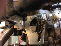
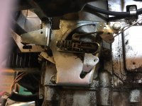
>> A lot of simple machines (like generators and stators) are reversible. When you rotate a generator, you get power out. But, if you put power into a generator it will rotate like a motor. Same for stators. If you move a magnet near a stator you get power out. But, if you put low voltage into a stator, then the coils turn into simple electro-magnets and will attract small steel objects.
The second simple test for stators is to take your Ohm meter and connect between the steel body and all the output leads. There should be zero connectivity. This is to make sure the coils are not "shorted" to the steel frame.
That's about the only 2 failure modes of a stator, and you can complete those tests easily within 5 minutes.
But if spending $85 is necessary for your well-being, then there's always my retirement fund !!