You are using an out of date browser. It may not display this or other websites correctly.
You should upgrade or use an alternative browser.
You should upgrade or use an alternative browser.
2010 Murray Electrical issue
- Thread starter BGS Mex
- Start date
More options
Export threadAuto Doc's
Lawn Addict
- Joined
- Sep 7, 2024
- Threads
- 20
- Messages
- 1,825
Hi BGS Mex,
I finally had a chance to print off the diagram and study it.
Print off the diagram that scrubcadet10 sent you.
The way I read the diagram, the "S" terminal white wire goes from the key switch to the clutch pedal switch and from there to the blade engage (attachment clutch) switch before it goes to the solenoid to trigger it for cranking the engine starter.
Just jumping the "B" red switch the "S" white wire at the switch will not crank the engine.
There is a clutch switch or blade engage switch or one of their connector pins that is having a problem. Possibly one of the switches are out of position. That is likely why you are having strange voltage readings, there is resistance/ voltage drop.
Yes that is the way I have read the diagrams too. I have been doing my testing with both the Brake/Clutch and the Blade Interlocks closed. The white pins on each (tested at the conductor side) Have continuity to each other when closed and the green at the seat interlock (closed) has continuity with the green on the blade interlock and with the A2 (green) terminal on the ignition switch (on or off). It also has continuity to the L (Yellow) terminal on the ignition switch in the OFF position. The grey at the seat interlock has continuity with the grey on the Brake interlock. I am just finishing a complete summary of all the testing I have done to date and will send it when I have finished.Hi BGS Mex,
I finally had a chance to print off the diagram and study it.
Print off the diagram that scrubcadet10 sent you.
The way I read the diagram, the "S" terminal white wire goes from the key switch to the clutch pedal switch and from there to the blade engage (attachment clutch) switch before it goes to the solenoid to trigger it for cranking the engine starter.
Just jumping the "B" red switch the "S" white wire at the switch will not crank the engine.
There is a clutch switch or blade engage switch or one of their connector pins that is having a problem. Possibly one of the switches are out of position. That is likely why you are having strange voltage readings, there is resistance/ voltage drop.
I agree completely with your "resistance/voltage drop". I just haven't been able to isolate it.

Auto Doc's
Lawn Addict
- Joined
- Sep 7, 2024
- Threads
- 20
- Messages
- 1,825
Can you connect a wire from the B terminal on the switch (with the battery connected) then touch it to the white wire pin on the solenoid to crank the engine? Key does not have to be on.
If it cranks that is bypassing everything and goes direct. If it does not crank, check the red wire for an issue getting power to the start switch. Trace the red wire back through all connections and verify they are clean and tight.
Also, I am not sure if the Husqvarna switch has the same internal pin contacts as the mower you are testing. Not all switches are the same internally.
Thanx again: I will try that this afternoon. I have tried a wire from the battery to the solenoid (White terminal) and the engine cranks. The Husqvarna switch has the same part number; I am used to this as parts usually aren't available here, so I have to be very careful. When I have a repair I make sure I have the correct parts diagram. I will be sending a PDF of my testing efforts.Can you connect a wire from the B terminal on the switch (with the battery connected) then touch it to the white wire pin on the solenoid to crank the engine? Key does not have to be on.
If it cranks that is bypassing everything and goes direct. If it does not crank, check the red wire for an issue getting power to the start switch. Trace the red wire back through all connections and verify they are clean and tight.
Also, I am not sure if the Husqvarna switch has the same internal pin contacts as the mower you are testing. Not all switches are the same internally.
Here is a report of the testing I have done. I will try to include all 3 documents. I will convert the other from word.
Attachments
The issue that I have is outlined in my testing documents. I get good voltage at the B (red) terminal and battery connection to the solenoid; but only 8.5 at the white (S) terminal. I will check this again when I try your suggestion.Thanx again: I will try that this afternoon. I have tried a wire from the battery to the solenoid (White terminal) and the engine cranks. The Husqvarna switch has the same part number; I am used to this as parts usually aren't available here, so I have to be very careful. When I have a repair I make sure I have the correct parts diagram. I will be sending a PDF of my testing efforts.
Well Here I am again. The good news is that the key switch will turn over the motor. I have no idea why! I will start putting things back tomorrow and see how it goes. Thank you so very much for your input; it really has helped my thought process. This became so frustrating for me.
Please note attached;
Please note attached;
Attachments
Auto Doc's
Lawn Addict
- Joined
- Sep 7, 2024
- Threads
- 20
- Messages
- 1,825
Hello BGS Mex,
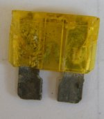
That fuse looks like an original and very weathered from age and exposure. It's been heated up a lot.
I hesitate to call victory yet because a fuse that has been repeatedly overheated. What this old fuse shows means it has had poor pin fit connections in the fuse holder. The fuse holder should be replaced as well.
It is never good to see a voltage difference below 10V when cranking but check against other similar mowers to see what you find.
Simple meter voltage testing and Ohm testing are what tricked you on this one. Yes, it has been a traditional method of testing for years, but there is one better for situations like this.
It is known as voltage drop testing. What is that? How is it performed? How can a meter show a reading on a single wire connection?
It is not a magic trick, but it is often not learned as other methods are.
There are many examples of this online and mostly performed on automotive applications, but the same thing applies to testing any mower starting or charging circuit for a voltage drop issue.
You are NOT measuring from power to ground; you are measuring actual power (voltage potential) loss on a single wire or cable connected from point A to point B. This is an easy way to also test for a poor battery post to cable end connections.
On this Murray mower design connect one meter lead to the battery positive terminal and the other lead to the "B" terminal of the switch, then try cranking (with plug wires off). See what your meter reads when cranking.
Here is an example at a rider battery with a corroded post connection:
 www.bing.com
Here is a file from the automotive All Data information that can help also:
That fuse looks like an original and very weathered from age and exposure. It's been heated up a lot.
I hesitate to call victory yet because a fuse that has been repeatedly overheated. What this old fuse shows means it has had poor pin fit connections in the fuse holder. The fuse holder should be replaced as well.
It is never good to see a voltage difference below 10V when cranking but check against other similar mowers to see what you find.
Simple meter voltage testing and Ohm testing are what tricked you on this one. Yes, it has been a traditional method of testing for years, but there is one better for situations like this.
It is known as voltage drop testing. What is that? How is it performed? How can a meter show a reading on a single wire connection?
It is not a magic trick, but it is often not learned as other methods are.
There are many examples of this online and mostly performed on automotive applications, but the same thing applies to testing any mower starting or charging circuit for a voltage drop issue.
You are NOT measuring from power to ground; you are measuring actual power (voltage potential) loss on a single wire or cable connected from point A to point B. This is an easy way to also test for a poor battery post to cable end connections.
On this Murray mower design connect one meter lead to the battery positive terminal and the other lead to the "B" terminal of the switch, then try cranking (with plug wires off). See what your meter reads when cranking.
Here is an example at a rider battery with a corroded post connection:
Voltage drop testing rider mower - Search Videos
Here is a file from the automotive All Data information that can help also:
Last edited:
Thanx again! I am certainly not celebrating yet. There still is the issue (in the wiring) that I haven't found. As you have seen from my testing report; where I get about 8.5 volts on the "S" terminal whether it is the Murray or Husqvarna ignition switch (Installed on the Murray) with either switch installed on the Husqvarna I get 12.68 Volts at the same "S" terminal! The (Murray) "B" terminal shows 11.8 volts and the battery 12.7 volts. Yet when testing at the Solenoid (disconnected) White wire it reads 11.46 Volts! It almost indicates a switch issue; except for the difference when installed on a different mower. I will keep messing with it this afternoon. This is making me far behind on other services! I will re-check all this stuff! I don't understand how the "S" terminal on the switch can be 8.5 volts and the white at the solenoid be 11.46 (Maybe I'm going blind while reading the meter!)Hello BGS Mex,
That fuse looks like an original and very weathered from age and exposure. It's been heated up a lot.
I hesitate to call victory yet because a fuse that has been repeatedly overheated. What this old fuse shows means it has had poor pin fit connections in the fuse holder. The fuse holder should be replaced as well.
It is never good to see a voltage difference below 10V when cranking but check against other similar mowers to see what you find.
Simple meter voltage testing and Ohm testing are what tricked you on this one. Yes, it has been a traditional method of testing for years, but there is one better for situations like this.
It is known as voltage drop testing. What is that? How is it performed? How can a meter show a reading on a single wire connection?
It is not a magic trick, but it is often not learned as other methods are.
There are many examples of this online and mostly performed on automotive applications, but the same thing applies to testing any mower starting or charging circuit for a voltage drop issue.
You are NOT measuring from power to ground; you are measuring actual power (voltage potential) loss on a single wire or cable connected from point A to point B. This is an easy way to also test for a poor battery post to cable end connections.
On this Murray mower design connect one meter lead to the battery positive terminal and the other lead to the "B" terminal of the switch, then try cranking (with plug wires off). See what your meter reads when cranking.
Here is an example at a rider battery with a corroded post connection:
Voltage drop testing rider mower - Search Videos
Here is a file from the automotive All Data information that can help also: