slewfoot2xm
Forum Newbie
- Joined
- Jun 17, 2014
- Threads
- 2
- Messages
- 3
Good times all,
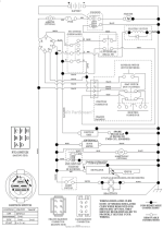
So I have a multimeter and I've tested a couple of things I'll list out what I've tested I believe I'm good with power up to the ignition switch then I'm not sure where to go from there.
Symptoms: Lawn mower doesn't start, doesn't attempt to start. Seated, with clutch / break depressed, all the way in start no sound (ie starter isn't even trying to start). No number display on the little LED read out that reads out hours. (please note lawnmower was running 2 weeks ago when i parked it, I've had the headlights disconnected for about a year that the only thing i haven't tested that i know how to test.).
Battery Terminals show 12,9 volts. Solenoid in shows voltage, both small wires on the solenoid show voltage. I checked the fuse inline, and confirmed good. Ohm meter tested good.
12+ volts in one wire . I traced the other wire up to the ignition switch, and I have power to the red wire there. That is also the other side of the fuse (used ohm meter to test resistance to it.
I'm not sure how to test the ignition switch or if there is anything else that i need to test.
Unfortunately I'm not sure how to test the solenoid. It has 2 larger posts, and 2 smaller connections. I"m assuming my issue is here, or in the ignition switch, but i don't know how to tell what to test next. I'm guessing there is a way to bypass the ignition switch.
The only thing that makes me think there is power going through the system is i can hear the noise that mower switch (up down plunger switch) makes when it engages / disengages. (what can i say i tried all the buttons but the lights).
suggestions and ELI5 appreciated, thank you.

