You are using an out of date browser. It may not display this or other websites correctly.
You should upgrade or use an alternative browser.
You should upgrade or use an alternative browser.
Export thread
Upgrading / Repairing steering front engined Rover Rancher
#1
M
mixotricha
M
mixotricha
Hello everybody. This is my first post.
I recently had a bit of a bingle with a tree and broke the steering sector gear in my Rover Rancher mower. Part A07693. I see that this part is no longer manufactured and am having problems finding a replacement. Since the mower has the engine in the front I am wondering what front steering options might be available. I do have access to lathe / mill and other tools. Just not sure what to look for to upgrade it. I recently upgraded the engine in the mower and also machined some custom pulleys so it goes much faster. So I would like to keep it and replace the obsolete steering parts with something else that is still available if I again have a bingle with a tree!
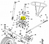
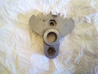
I recently had a bit of a bingle with a tree and broke the steering sector gear in my Rover Rancher mower. Part A07693. I see that this part is no longer manufactured and am having problems finding a replacement. Since the mower has the engine in the front I am wondering what front steering options might be available. I do have access to lathe / mill and other tools. Just not sure what to look for to upgrade it. I recently upgraded the engine in the mower and also machined some custom pulleys so it goes much faster. So I would like to keep it and replace the obsolete steering parts with something else that is still available if I again have a bingle with a tree!


#2
B
bertsmobile1
B
bertsmobile1
Not much you can do there as this is one of the Made In Australia models and Rover went to rebadging imported mowers 2 if not 3 owners ago.
New owners are not obliged to carry parts for previous owners products.
The gear can be welded with some hard facing alloy then have the the teeth recut or you can chase up a "prototype & one of " engineering company to cut you one from solid then get it heat treated I built up one but the resale on these is not sufficient to warrant the costs of repairing the gear.
It is a fairly common failure I have the remains of 3 in the junk pile , all with gears like yours and the story is the same with the rear engine riders .
Some of the very old MTD's ( also sold as Rover & Victa ) had above the floor steering but universally every new mower uses under floor steeringasnd there is not enough clearance around the belts to do that to your Rover.
To go under floor you would have to replace the cast iron stack pulley on the engine for a longer one or space yours down the PTO shaft.
Then when you do that you will limit the cutting height before the deck fouls on the transmission .
Below is the set up Greenfields used up until the end of the Aniversary series , around 1980. it should work very well on your Rover
How many of the parts available new is unknown as Greenfields went bust in 2018 & were taken over by Cox & I have no idea how many legacy parts Cox are going to supply although they are still making the last Fast Cut
There are lots of old Greenfields around so you might find a donor mower with a blown engine at a reasonable price but running Aniversary models are still selling for $ 2000 to $ 5000 .
I am fairly sure that the Greenfields king pin ( # GT 7230 ) either swaps strait over or can be modified to fit without major problems as the front cross members are fabricated from the same size sections of bar & tube.
In any case you should be able to fabricate some thing based on the photos below
IF you want the detail scan of the steering gear IPL then PM me & I will send you a copy
It is basically a bell crank to rotate the left right movement of the steering arm on the bottom of the steering shaft into a front back motion to the king pin then the same on the king pin. The original bell crank was 2 strips of flat strap welded together but some time they changed to the triangle of 1/4" thick flat plate
After that is is just strait rods with ball ended tie rod ends ( very important ) so it will be a case of cut some rod to fit & thread it.
The existing tie rod between the wheels should remain
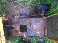
Over all view
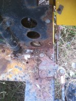
Steering stem end & Bell Crank
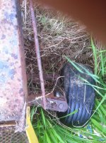
King Pin Detail
Steering rod on top & tie rod on bottom
And before you ask,
Yes this is from my graveyard
No it is not for sale
It is waiting for me to make a 1/2" stand off plate to mount a new OHV engine to so it clears these steering gear & some more bushes for the deck lift arms
Then it is a cost of paint & onto Evilbay for $ 5000
last one sold in 2 hours but I do give 12 month warranty on them .
New owners are not obliged to carry parts for previous owners products.
The gear can be welded with some hard facing alloy then have the the teeth recut or you can chase up a "prototype & one of " engineering company to cut you one from solid then get it heat treated I built up one but the resale on these is not sufficient to warrant the costs of repairing the gear.
It is a fairly common failure I have the remains of 3 in the junk pile , all with gears like yours and the story is the same with the rear engine riders .
Some of the very old MTD's ( also sold as Rover & Victa ) had above the floor steering but universally every new mower uses under floor steeringasnd there is not enough clearance around the belts to do that to your Rover.
To go under floor you would have to replace the cast iron stack pulley on the engine for a longer one or space yours down the PTO shaft.
Then when you do that you will limit the cutting height before the deck fouls on the transmission .
Below is the set up Greenfields used up until the end of the Aniversary series , around 1980. it should work very well on your Rover
How many of the parts available new is unknown as Greenfields went bust in 2018 & were taken over by Cox & I have no idea how many legacy parts Cox are going to supply although they are still making the last Fast Cut
There are lots of old Greenfields around so you might find a donor mower with a blown engine at a reasonable price but running Aniversary models are still selling for $ 2000 to $ 5000 .
I am fairly sure that the Greenfields king pin ( # GT 7230 ) either swaps strait over or can be modified to fit without major problems as the front cross members are fabricated from the same size sections of bar & tube.
In any case you should be able to fabricate some thing based on the photos below
IF you want the detail scan of the steering gear IPL then PM me & I will send you a copy
It is basically a bell crank to rotate the left right movement of the steering arm on the bottom of the steering shaft into a front back motion to the king pin then the same on the king pin. The original bell crank was 2 strips of flat strap welded together but some time they changed to the triangle of 1/4" thick flat plate
After that is is just strait rods with ball ended tie rod ends ( very important ) so it will be a case of cut some rod to fit & thread it.
The existing tie rod between the wheels should remain

Over all view

Steering stem end & Bell Crank

King Pin Detail
Steering rod on top & tie rod on bottom
And before you ask,
Yes this is from my graveyard
No it is not for sale
It is waiting for me to make a 1/2" stand off plate to mount a new OHV engine to so it clears these steering gear & some more bushes for the deck lift arms
Then it is a cost of paint & onto Evilbay for $ 5000
last one sold in 2 hours but I do give 12 month warranty on them .
#3
M
mixotricha
M
mixotricha
So I think I understood the picture? Rather than a gear does it just have a linkage from the steering shaft to the plate ? I was wondering about just putting another linkage in. I know the sector gear also gives a bit of reduction. Talking to an old lecturer of mine that is good with the physics about this now. Have I understood properly that this setup has no sector gear in it? It isn't the kind with the sector gear underneath? Just another linkage and that plate out to the right? If that is the case what an earth was Rover thinking! Hah!
Thanks for the in-depth response mate. I appreciate it. This has been really helpful.
If I have understood this right I can do this setup easily with all the tools I already have.
Thanks for the in-depth response mate. I appreciate it. This has been really helpful.
If I have understood this right I can do this setup easily with all the tools I already have.
#4
B
bertsmobile1
B
bertsmobile1
Probably
The Greenfields set up was all flat bar , round bar & welds
The killer will be if you have enough space between the steering shaft # 2 and the back of the crankcase to attatch a bar as per the photo
Of not then you could put a sprocket on the bottom of # 2 and another sprocket in place of the bell crank with a short chain between them
do them 2:1 or 3:1 so the steering is not quite so direct .
Again standard stuff from any engineering supply shop
If you go the sprocket route drill a hole through the sprocket & shaft # 2 and then secure the sprocket with a roll pin ( use a big one )
Once that is done you should be able to bolt the original tie rod # 110 to either the bell crank or sprocket
So the only new parts required will be the tie rod between the steering shaft and the bell crank / sprocket plus the bell crank or sprockets depending which way you go
OR even a sprocket on shafts # 2 & # 3 joined with a short chain
All depends upon how much space is under the dash to play with
Just remember keeping tension on a short chain is very difficult
If you go for a longer chain then you could put a sprung tensioner between the two sprockets to allow some give in the system in case of another collision .
#5
B
bertsmobile1
B
bertsmobile1
While it is highly unlikely that there will be another poster with the same problem, some photos of the final outcome would be appreciated.
People get hung up on not being able to find parts for older mowers when there is generally an easy work around .
People get hung up on not being able to find parts for older mowers when there is generally an easy work around .
#6
M
mixotricha


M
mixotricha
I took the console out and did some measuring and then had a go in the cad at trying to come up with a layout that would let me use a linkage. No matter how I move it about I really can't seem to find the space. First thing to note is that on the left hand side the linkage for the cutter engagement comes up out of the bed. So any plate in the linkage would need to come up above that. Then it sticks in to the foot area. If I flipped the king pins over at the front ( which I think might be possible ) then I might just have space on the right. It starts to seem complicated. Then the linkage down the side of the mower will need to be shortened.
Starting to seem like making a new gear might be easier. I am contemplating going at that three possible ways. One would be to get the basic shape plasma cut somewhere. But I am having trouble finding a place in Australia to do a single plasma cutting job for me. The other would be to be to profile cut it myself on my mill. But might take forever and is going to be a lot of work. Drawing up a basic shape that is pretty close to the original gear wasn't a problem. The other option I was thinking of was to get thinner sections of the gear laser cut ( say 4mm ) and then laminate them together in to a new gear with some rivets. Then heat treat the teeth. The steering shaft itself is fine. It was the gear that busted.
I also did think about a sprocket arrangement. And also I saw a ride on mower ( EL36 Rider ) that had a sector gear and a separate pinion that slid over the steering shaft.
Attachments
#7
B
bertsmobile1
B
bertsmobile1
OK,
So you have some gear there to work with
In that case I would just get a pair of chain sprockets and slip them over shafts # 2 & # 3
That would be the easiest thing to do
Latter Greenfields and all Cox mowers use a chain for steering
Just machine out the centers of the sprockets to slide over the shafts
You sound like a compitent machinist so you could weld then above the steering arm on shaft # 3 thus allowing original parts to be fitted at a latter date should they become available
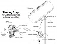
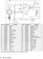
It would be cheaper just to buy the sprockets and machine them to fit than to buy propriorty parts but FWIW this is the current Greenfields set up
While it is installed under floor there is no reason why it could not be done above floor
Note the sprocket on the steering shaft is machined directly into an upset in the end


#8
M
mixotricha
M
mixotricha
That is a great idea. I had wondered about a sprocket setup as well but I was not sure if I would be able to tension it. But now that I think about it what I would do is split the bottom plate that carries both the steering shaft and the secondary shaft. Then I could side each plate away giving more distance between centers of those shafts. Then a rod somewhere will need adjusting but I can probably just bush mechanic some solution for that up! I also have an idea what to do about stops that doesn't involve that plate or grooves in the gears. Much simpler solution.
But my next question would be if you know what the OD of that GreenField/Cox steering shaft is?
Quick look on ebay showed me a pinion and says it is a 5/8" center hole?
Both the shafts in the rover setup are about 19mm.
If they both have a smaller ID than 19mm that would mean just machining them out and no need to make bushings. Also means I don't need to go through process of selecting chain etc etc.
#9
M
mixotricha
M
mixotricha
I just looked at the plate that carries both shafts again. I think it has an adjustment on it anyway that may be enough to let me tension a chain setup.
#10
B
bertsmobile1
B
bertsmobile1
Bucketing down rain at the moment
When it stops I will see what is in the graveyard so might be a couple of days
The Greenfields large sprocket pivots on a 3/8" grade 9 bolt and the pinion is machined into the steering stem.
The Cox set up is different again as they use a chain from the steering shaft all the way to the front axel
So I don't think any of the actual mower parts will work for you they were just there to illustrate how they did it .
However Cox have just redone their web page so you can actually find stuff
The IPL's are at the back of the owners manual
cox mowers
CBC sell plain sprockets as do McPhersons .
Most bearing shops keep a range of stock sprockets
#11
M
mixotricha
M
mixotricha
Think I might go with a drive sprocket off a bike. I have lots of those about in a box somewhere with different size holes. Also lots of 420 chain to fit em. Found a smaller looking pinion on the fleabay that is also 420. Now just trying to remember where all my chain pin pushing tools and other sprocket related bits went.
#12
B
bertsmobile1
B
bertsmobile1
420 might be a bit big to get a reasonable leverage but what the heck,
using what you have sounds like a plan Stan
using what you have sounds like a plan Stan
#13
M
mixotricha
M
mixotricha
So some digging about in my junk box found something interesting.
After looking at lots of drive sprockets and some bicycle cassette sprockets in my junk pile are all the same pitch as some cox steering chains I came across.
According to some blurb for a steering chain on ebay ...
Width between Plates: (inches) 3/16"
Pitch (inches) 1/2" (mm): 12.7mm
86 links including con-link
Or in other words lots of mowers about with that pitch but the chain is thinner. Thicker chain seems fine to me.
Sprocket I looked at off a bike was actually 19mm hole just splined to.
I think it will slide straight on to the secondary shaft thing'a'wazut and bolt on thar if I just braze in the existing holes on the thing'a'wazut and drill new ones.
Also looking at the ratio for the cox steering setup it doesn't really look to be all that much either.
So I can get a 420 at say 10T and another 420 at say 20T. I think it will do the jerb you know.
Then the aluminium base plate they go in to splits so it can move further.
That means the hole in the console for the thing'a'wazut also needs to shift.
Tomorrow I will take some pictures of what I mean.
#14
B
bertsmobile1
B
bertsmobile1
I got you
If you asked I would have said the steering chain was 5/16 x 1/4 just goes to show it is good to check
I must admit I had never thought about doing this so it might get me enthused to get some of the colts I have sitting in the grave yard running & sold
I was thinking along the line of fabricating some gears when we get the Adcock running but sprockets & chains might just be the go
Just goes to show how helping others can help yourself .
#15
M
mixotricha

M
mixotricha
Today I turned out the hole in the drive gear. The hole itself was 19mm but of course splines. Splines were hardened. Lathe is currently in pieces so I drilled it out. Think it tore up my nice Christmas tree bit to! What worked nicely was to just grind the splines away. Slips on the thing'a'wazut fine. Also plenty of room to put bolts through it in to the arm of the thing'a'wazut. Was also thinking about the ratio and how can probably come up with some way to shorten or lengthen that arm if needed. The plate that carries both shafts I am thinking about spitting. The thing'a'wazut shaft is in a rotating cam arrangement but it might be enough for keeping the tension nicely. Will have to wait till I put it together to see. I am still thinking about the stop for this. I am thinking it will be something on top of the thing'a'wazut shaft where it pokes through the top of the frame in the console. I've also ordered up a pinion that has a 19mm ID so hopefully it just slides on. If not I will be mowing my lawn by hand till the lathe is fixed 
Also I have no idea about the twist in the thing'a'wazut. I think it was that way before this lot tore up.
Also I have no idea about the twist in the thing'a'wazut. I think it was that way before this lot tore up.
Attachments
#16
B
bertsmobile1
B
bertsmobile1
looks like a goer
parts book shows the twist which is to keep the tie rod ends in a flat plane.
A simple U bolt over the top of the arm or something similar will do the job of a stop
If you are a dab hand with the welder then weld a bolt between the sprocket teeth to prevent the chain engaging, although this will tend to stretch the chain.
According to the wrong IPL for your mower the Wasit is called a Steering lay shaft .
#17
M
mixotricha
M
mixotricha
As soon as the pinion turns up in the post I will come back and update this. Should be next week some time based on the tracking.
#18
M
mixotricha


M
mixotricha
Sorry it has taken awhile to come back to this. Got the front end reassembled. It is almost good to go _but_ the ratio is not quite enough. Close but not quite. Now the main problem with all of this really is the placement of the engagement for the clutch for the cutter. I went in to the local mower shop and they said look at parts for a model 2300 Nova / Supa Nova and gave me a parts diagram and list for that. But before that I am just going to figure out how to move the engagement lever for the cutter clutch. If I solve that problem and I can put in any steering I want really. It interferes with the arm on the layshaft if I move the layshaft over any further See I split the plate that carries the steering shaft and the layshaft. I then put slots in it so I could slide it. I'll use some sort of adjustment like the wheel adjusters off an old bike. I'll take a picture of the fully assembly when I go back out to the shed again. I was about to quit on this before I thought of moving the engagement lever. But with the front end up in the air the wheels turn nicely. It just doesn't have quite enough torque to turn em nice on the ground. They turn but it is heavy. Needs about 10 more teeth in the driven gear I think.
Attachments
#19
B
bertsmobile1
B
bertsmobile1
That sounds very wrong to me
Cox Drive the deck from the rear double pulley so when you hit something hard with the deck or blades the deck goes back and the belt goes slack so it slips rather than breaking which is how the get away with a $12 std belt rather than a $ 100 kevlar belt .
It is one of the prime reason I use them for loaners , however they are Orions & Compacts, not Nova & Super Novas .
Novas & Super Novas also drive the deck from the rear so you engage the deck by allowing the springs to pull the deck forward to tighten the belt.
Rover drive the deck from the front double pulley so the deck is engaged by sliding it back to tighten the belt
So I don't see much from the two interchanging
#20
M
mixotricha

M
mixotricha
Ah my explanation was not clear. What I was saying was that I looked at bigger drive sprockets like on the Supa Nova. This makes sense to because if one imagines the sector gear that came out of the Rover then it then it would be about 120mm in size as a full gear. Now I have space for the diameter of a bigger gear but when that happens the Layshaft needs to move over. It seems to me Rover was not entirely rubbish here. What they did was a very good way to get a large ratio in a small space. They understood you only need a small segment of the larger gear. However this could also be solved by me changing how the engagement for the cutter works. Since that is what is in the way. I am thinking a cable. But I can't quite place in my mind what that cable is out of. Pulls and twists and locks. I might be thinking of a parking brake in the dash board of some old car I once had. As soon as I remember what it is I am going to get rid of the engagement lever it has for the cutter and replace it with a cable and a handle in the console. It pulls an arm down below that swings the engagement pulley over. Bit of tension on it but not to much. Then will have space for bigger gear. At least this is my plan. See as it is now it 'just' has clearance and with the wheels off the ground turns nicely. Just not quite enough torque when on the ground to feel good. Can turn em but to heavy. Can feel the stress in it on the chain. Is a ratio of about 1.5 is to small. Needs to be more like 2.5.
Attachments
#21
M
mixotricha
M
mixotricha
Of course the alternative would have been to swap the steering over so that it came out the right side of the mower instead of the left. But the way Rover designed the steering it cannot be flipped. At least not that I can see. Also the tracking arm on the steering isn't on a spline! What I did to get around that was to rotate it 180' with the split on to the key. That is a bit dubious so I might end up putting a tapered pin through it when I am done or similar.
#22
B
bertsmobile1
B
bertsmobile1
Move the sprockets higher ?
Gees, the steering gear for a 1980's super nova still availible .
These mowers really do run forever
Gees, the steering gear for a 1980's super nova still availible .
These mowers really do run forever
#23
M
mixotricha
M
mixotricha
Yeah that was my thought to. But what happens is the linkage out to the front/tracking arm contacts the motor. You get a narrow area of clearance out to the front steering arm where the linkage doesn't hit anything. So it seems to me that removing the engagement lever to a different setup is the other way to solve this problem and would enable any steering to be fitted really. I am pretty sure what I am hunting for now is an old pull and twist parking brake out of something. I might even have one in a box somewhere. So far I have spent 35 bucks on this. Bit of time into it now. But keeping the acres down with the hand mower is going all right. So will keep mucking with it. Almost got it right. Worth noting that if I had not flipped the steering arm about at the front like I did the wheels would turn to opposite lock the way it is setup. I tried to think if I could flip the steering over at the front. But I cannot really see how. Can you think of any old mowers like this where the steering came out on the right ( from drivers position ) rather than the left? I did contemplate cutting up the spindle and physically flipping the orientation of the arm. I suggest this because nothing at all is in the way on the right.
#24
B
bertsmobile1
B
bertsmobile1
No they all steer either from the left or from the middle.
And yes I know the clearance problems with the engine which is why I have to raise the engines to get the OHV's to fit in the earlier SV Greenfields
The latter Cox & Greenfields have the sprocket in front of the engine pulley so the steering gear does not foul on the drive belts. Another option would be a third shaft on the other side of the steering shaft with 2 sprockets on it so the chain would go from the steering shaft to the new layshaft, get a 2:1 or higher reduction there then from the new layshaft to the original lay shaft
How many old sprockets you got laying around ?
OTOH check the king pins, they would probably swap over but that would have the tie rod in front of the mower where it would be vunerable
#25
M
mixotricha
M
mixotricha
What I did in the end was just dump the whole mess. The sprockets. All of it. Put a big lever on the side. Bit like a skid steer. Works amazingly well and feels nicer than the original steering. Some things I noticed about this were that I can now steer the mower while pushing it from behind. Also can lean over and pick stuff up off the ground. I'll take a picture of the set up next time I go out to mow the lawn. To fix this in the end was not more than some old fashioned metal bashing heating and bending. Big lever. Bracket to hold it in. Bit of extra strength added to the area that it pivots on. What would finish it off nicely now would be to put the throttle on the steering arm. Also I now need to do the brake pads in the Peerless transmission
#26
B
bertsmobile1
B
bertsmobile1
Well a long lever would give a bigger reduction ratio than the tiny steering wheel.
I had a couple of Cox Compacts with a long handle welded onto the F-R pedal, such that it was uncomfortable to sit on the mower with your foot on the pedal.
I had always thought it was some sort of dissabled work around.
Then when in town I was a caravan dealer with a similarly modified mower using it to shuffle vans around the lot and it all made perfect sense as the lever was very comfotable to use if you were walking beside the mower
So I did the same with a Greenfields to mow the steep verge as they have a left side discharge and an east-west engine mounting so I can safely mow across a slope.
Sold it last year to a customer who had lost his right leg .
He has never stopped thanking me for it .
He uses it for exercising walking next to it and when he gets tired jumps on and mows.
