You are using an out of date browser. It may not display this or other websites correctly.
You should upgrade or use an alternative browser.
You should upgrade or use an alternative browser.
Export thread
Need LA110 wiring diagram for engine swap
#1

derost
derost
Hey there,
I've got an LA110 with a blown engine so I am throwing in an FB460V from a "running but with no brakes" 160 I have. I have a wiring diagram for the 160 but not for the LA110. I'm more than happy to purchase it, especially if its a down load since I'm knee deep into things, but I can't find one anywhere. Thoughts???
Thanks in advance for any help offered...
Doug
#2
B
bertsmobile1
B
bertsmobile1
There is only 1 or 2 plugs that connect the engine to the mower
You have both the mowers so take the blower housing off and see where they go to.
It will be the same for both engines provided that both have the same type of magneto coils ( single small wire ) .
The other plug will be for the electric PTO is you have one .
Usually there will only be 3 or 4 wires connecting the engine & the mower
1) Coil kill wire ground or open circuit
2) carb solenoid wire open or 12 V with key on ( some have an extra ground for this )
3) Rectifier 12 V goes back to the battery to recharge ir
4) starter solenoid , on plug if the mower has a piggy back solenoid, not there for remote solenoids .
#3

derost
derost
Thanks very much for the reply!
1) So the engine I am putting in (Kawasaki FB460V-BS00) has 2 wires going to the stator while the B&S coming out has only 1.
2) There is a set of wires going to the float bowl on the B&S coming out, nothing on the Kawi going in.
3) On the LA110, right off the + on the battery it first goes into a block with some purple wires going into it... is that a safety or neutral start switch? The Kawi has an older version of that connected to the starter and I don't want something doubled up of course.
4) The Kawi uses a voltage regulator... does the 110 have one?
I've attached a copy of the wiring for the Kawi if that helps...
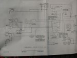

#4
B
bertsmobile1
B
bertsmobile1
1) what colour is the single wire & the plug on the end of it .
The B & S should have had a regulator / rectifier some where , usually on the dip stick tube .
IF so the single wire plugs into it and the other wire coming out of the rectifier goes to the red wire on the 6 pin plug .
2) The solenoid needs 12 V to open so should be wired to the yellow wire at the 6 pin plug .
You will need the plug off the old mower and the ground wire which usually goes to a screw on the cooling ducting
For simplicity you can be replaced the solenoid with a plain bowl bolt as used on the walk behinds but you will be contravining EPA regulations and destroying all life in the universe .
3) The purple / white should be battery voltage only when the key is in the stat position so that goes to the remote starter solenoid which you will have to transfer from the other mower as well .
4) The green wire on the alternator plug should be open circuit with the key on & closed circuit with the key off .
If so it goes to the magneto . double check that one before you connect it with the engine running just to be sure.
There must never be voltage on the kill wire or it kills the timing chip
#5

derost
derost
Once again I thank you for all of your time, this is a huge help...
1) The single wire on the B&S is yellow with a white barrel plug. Yes, there is a R/R on the dipstick with the corresponding barrel plug, a red wire that goes to the harness, and a black ground wire.
2) The solenoid on the Kawi has a solid purple and a red wire coming into it from a relay (vf4-55f11-s01) with another solid purple going back to I assume neutral or seat switch, and then a black ground. Do you think this relay is no longer needed? Looking at the 6 pin, there is a yellow coming from the harness, that on the other side of the plug goes to a grey wire with a double barrel plug that is shared with a black ground. This plugged into the bottom of the original carb bowl, and black to ground (of which the Kawi carb can not accommodate). When you say yellow wire at the 6 pin, do you mean the yellow wire from the dip stick tube R&R, and run that to the solenoid, doing away with the relay I mentioned?
OK, I made a quick diagram of the 2 set ups to hopefully better explain things...
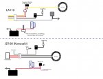

#6
B
bertsmobile1
B
bertsmobile1
The purple wire on the 160 should be the trigger wire to the starter solenoid and should go battery voltage when the key is in the Start position
So it goes to the trigger post on the remote starter solenoid for the Briggs engine the relay YF4-5511-SO1 is now surplus.
If you look at the full circuit diagram you originally posted you will see the purple wire ultimately ends up at the S on the key switch after going through all of the safety switches so the engine can not crank unless the PTO is off and the brake is on .
The Ignitor on the 160 is also redundant because the ignitor chip is embedded within the coil on the Briggs engine
Thus the green wire will connect to the back wire on the Briggs engine.
The unknown do dad near the battery is a solenoid switch .
If it interrupts the battery starter cable, bypass it .,
#7

derost
Sorry for the delay... work and such.
Reading your response I can't help but question if you have the engine swap going in reverse? The Kawasaki from the 160 is the good engine, and going into the LA110 with the blown B&S engine. My questioning is because:
1) You state that the purple now goes to the starter on the Briggs and the relay is of no use.
2) ... the ignitor chip is embedded within the coil of the Briggs.
What I see so far is that
1) The thing I notated next to the battery in the LA110 diagram is actually controlling the starter so when the key is turned, it clicks loudly and sends 12v to the starter. SO... I guess I don't need the relay or the purple wire to connect to the 160 starter, I can just run this power to it.
2) Next thing is the alternator. The 160 uses a voltage regulator, so I assume I must wire that into the 110. I can pull the power off of the starter solenoid, disregard the yellow low fuel lamp wire, black to ground, red/ whites stay going to the alternator, green goes to ..... ??? hhhmmm... it states it connects to ground at the switch when in off position. When I look at the 6pin on the LA110, I have red/ black with constant 12v, yellow with 12v at key "on", yellow/ white and white. If I had to make a guess I would say green to white as the white on the 110 originally connected to the coil... but that is a weak guess.
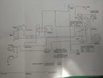
derost
The purple wire on the 160 should be the trigger wire to the starter solenoid and should go battery voltage when the key is in the Start position
So it goes to the trigger post on the remote starter solenoid for the Briggs engine the relay YF4-5511-SO1 is now surplus.
If you look at the full circuit diagram you originally posted you will see the purple wire ultimately ends up at the S on the key switch after going through all of the safety switches so the engine can not crank unless the PTO is off and the brake is on .
The Ignitor on the 160 is also redundant because the ignitor chip is embedded within the coil on the Briggs engine
Thus the green wire will connect to the back wire on the Briggs engine.
The unknown do dad near the battery is a solenoid switch .
If it interrupts the battery starter cable, bypass it .,
Sorry for the delay... work and such.
Reading your response I can't help but question if you have the engine swap going in reverse? The Kawasaki from the 160 is the good engine, and going into the LA110 with the blown B&S engine. My questioning is because:
1) You state that the purple now goes to the starter on the Briggs and the relay is of no use.
2) ... the ignitor chip is embedded within the coil of the Briggs.
What I see so far is that
1) The thing I notated next to the battery in the LA110 diagram is actually controlling the starter so when the key is turned, it clicks loudly and sends 12v to the starter. SO... I guess I don't need the relay or the purple wire to connect to the 160 starter, I can just run this power to it.
2) Next thing is the alternator. The 160 uses a voltage regulator, so I assume I must wire that into the 110. I can pull the power off of the starter solenoid, disregard the yellow low fuel lamp wire, black to ground, red/ whites stay going to the alternator, green goes to ..... ??? hhhmmm... it states it connects to ground at the switch when in off position. When I look at the 6pin on the LA110, I have red/ black with constant 12v, yellow with 12v at key "on", yellow/ white and white. If I had to make a guess I would say green to white as the white on the 110 originally connected to the coil... but that is a weak guess.

#8
B
bertsmobile1
B
bertsmobile1
No reason to appologise .
No one has died because a post was not responded to.
Yes I got it backwards
Easy bits first
The solenoid near the battery is redundent so bypass it by putting both cables on the same post
The briggs starter uses a remote solenoid with an inertia pinion on the starter but the Kawasaki engine has a throw out solenoid where the solenoid itself pushes the pinion gear into the flywheel teeth .
So that single Purple wire ( which should show battery voltage with the key in the S position only ) needs to go up to the tab on the Kawasaki engine where the purple wire was connected to.
The magneto kill wire on both engines just goes to ground so the white wire on the 110 that used to go to the black wire on the B & S will now go to the White wire on the Kawasaki before the igniter
So white to white at the plug easy .
Assuming you are using the Kawasaki rectifier regulator the old carb solenoid wire ( gray on the B & S ) will go to where the yellow wire is connected to the kawasaki rectifier.
The rectifier may need a voltage signal to close the charging circuit when the mower is turned on which the yellow wire would provide .
The tell tale is where the DC + wire from the rectifier goes to.
IF it goes to the key switch then the rectifier is usually not switching because the key takes it in & out of circuit
If it goes directly back to the battery ( usually via solenoid hot wire ) then it requires some thing inside the rectifier to turn it off to prevent the alternator trying to become a motor when the engine is off .
The solid red wire from the rectifier will go to the hot ( battery ) terminal on the starter solenoid to send power back to the battery.
#9

derost
derost
TERRIFIC!
Looks like I've got everything,
- White to white.
- Grey on 6 pin (coming off of yellow) to yellow on rectifier
- Black on 6 pin (coming off of white) to green on plug which turns into white for the kill wire.
- Power directly from battery to starter solenoid.
- Purple from solenoid next to battery (which is now completely bi-passed) directly to starter solenoid instead of using relay. (There was also a pair of black wires connected there... are these just grounds that can be disregarded, or should they be connected somewhere, to the frame if they are indeed grounds..)
Just want to verify the solid red from the rectifier ...
1) The solid red from the rectifier... you say connect it DIRECTLY to the starter solenoid?
Originally, the red went to a breaker first, then on to the starter solenoid from the same post, with the other post of the breaker being a red/ blue that went to key when in run position (B&A). Should this be connected back in? If so, would the red/blue also be connected to the yellow?
MOST IMPORTANTLY!
I want to Paypal you beer money for all of your time and effort!
My wife and I just bought our dream home on 4 acres, and as with all new home purchases the additional costs keep adding up. I had a couple of friends throwing away these tractors, and my goal is to get one tractor running since I have a plow for it. Our driveway is 500' long and with my snow blower it takes 3 hours if not too deep... even if this doesn't speed it up, at least I'll be sitting down!!! Wisconsin winters can be boogers....
#10
B
bertsmobile1
B
bertsmobile1
Dosen't work like that .
We do what we do for our benefit in solving problems .
If we wanted to be paid there are tons of fee for service web sites we could be on .
A simple thank you is fine or a stuff you if it all goes pear shaped .
According to the circuit diagram the return line ( red ) does not go through the breaker which is on the other mower
So working on the KISS principle you may as well leave it there unless you run the power through it .
#11

derost
derost
Yes yes, of course, my bad... my intention certainly was not to offend, and I am sincerely grateful for your help so there will not be a stuff it from this end I assure you!
All is hooked up as diagramed, and with the turn of the key all I am getting is a click at the starter... the solenoid is reacting but the starter is not.
I verified I am getting 12V on the red at the starter solenoid, and 12v on the purple when the key is in start position. Thoughts?
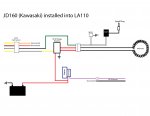
All is hooked up as diagramed, and with the turn of the key all I am getting is a click at the starter... the solenoid is reacting but the starter is not.
I verified I am getting 12V on the red at the starter solenoid, and 12v on the purple when the key is in start position. Thoughts?

#12
B
bertsmobile1
B
bertsmobile1
No way in the wild world could you offend me.
I learned a long time ago taking offence was a zero sum game.
The solenoid should have a bridge wire to the starter
check it is getting power when the solenoid is energised.
Might be worthwhile to pull the starter off to check it.
I have seen people modify a throw out solenoid to work with a remote solenoid because the contacts were burned out
SO they kept the throw out to engage the starter gear and remotely energised the starter motor .
#13

derost
derost
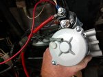
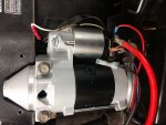
The starter is new, and only used a dozen times before switching tractors... attached is a picture of the connection. I know it looks like the white wire is connected, it's not, just in the background at the perfect angle. The only wires hooked up to it are the direct power from the battery, the red from the regulator, and the purple.
I am getting constant 12V coming in from the battery; the purple wire is also getting 12v when keyed to start.
I am still questioning the black wires (pictured) that run with the purple if these are grounds? One of them runs back and splits to become 3 black wires if that helps identifying....
I assume that when energized, the solenoid essentially sends power from one post to the other. The "other" is not getting power when the solenoid is activated, so the starter is not getting its power. Aside from checking for flaws on the exterior, is there anything on the inside of the solenoid that's accessible?


#14
B
bertsmobile1
B
bertsmobile1
OK, things are starting to make sense
If the trigger wire is not causing the heavy battery cable to energise the starter, try jumping to the "other" battery cable
If the starter spins then the solenoid must just be a throw out for the starter pinion or it has an internal contact problem
You say it was working before
How was it wired ?
Through the external solenoid ?
