LTX1045 Won't Charge Battery

CubCadet1045

Forum Newbie
Joined
May 3, 2020
Threads
1
Messages
4
I bought a used LTX1045 that runs but won't charge the battery. After running it for 15-30 mins if I stop it I need to recharge the battery before I can start it again. I think the problem is with the purple wire from the rectifier as it is not connected to anything. While I was looking for where to connect it some of the other wiring seemed odd to me. Can someone tell me what should be connected where. I do not want to put it together wrong and fry something.


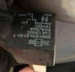
Purple wire end of the rectifier not connected to anything. Where should this connect? Am I correct that this is my charging problem?
Wires (798x1280).jpg


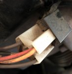
The brown wire on the left looks like it was a connector that should have been in a harness connector that then had a spade connector crimped over it. Is this connection correct?
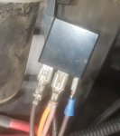
Relay Crushed Connector.jpg

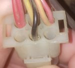
The main wiring harness has 4 of 6 pins filled. The matching connector only has 3 of 6 pins filled. Only 2 of the pins between the connectors make connection. The pins/ wires from the bottom row do not match up. This seems odd to me.
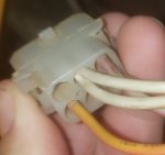
Does anyone if my harness ends are correct? Should the purple wire from the rectifier connect into this connector?

Main wiring harness end
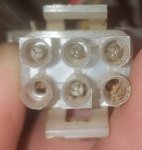
Main Harness End Front.jpgMain Harness End Back.jpg

Wiring harness end
Harness End Front.jpgHarness End Back.jpg


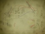
Sketch of how wiring looks. I may have mixed up the brown wires from the rectifier to the relay. The pins they go to on the relay may be flip flopped.
wiring-960x1280-jpg.52035


Thank you in advance for you help.
 

Attachments

  • Wiring (960x1280).jpg
    Wiring (960x1280).jpg
    483.9 KB · Views: 18

bertsmobile1

Lawn Royalty
Joined
Nov 29, 2014
Threads
65
Messages
24,995
The relay in your hand drawn sketch shorts out the alternator so it acts like a brake when you turn the engine off >
this was a common set up before the electric PTO clutches were fitted with a brake and on some engines before the carb solenoid was fitted to reduce the amount of unburned fuel released into the atmosphere.
It is of little use but on the other hand it also does little damage.
The puuplr wire should be the DC output from the rectifier.
Check it with the engine running it should show around 14V DC with the engine at full speed ..
If not the rectifier might need replacing .
If it is good then the purple wire will go to one of the terminals labled as A ( alternator ) on the back of the key switch .
The terminal should be connected to the B terminal ( Battery ) with the key in any running position and be open circuit with the engine turned off .
 

evh

Member
Joined
Nov 25, 2019
Threads
5
Messages
47
Here are pics from my 2009 LTX-1045
 

Attachments

  • Shot1930.jpg
    Shot1930.jpg
    139.7 KB · Views: 5
  • Shot1931.jpg
    Shot1931.jpg
    64.1 KB · Views: 5

StarTech

Lawn Royalty
Top Poster Of Month
Joined
Feb 19, 2020
Threads
91
Messages
11,428
Okay on the mower side connector the red and orange (maybe yellow) wires wires tied together terminal should have 12 v on if I thinking correctly. IF so then Purple wire goes in the matching hole on the engine connector. (hole to left of the white wires and above the yellow wire). Now that depends things being wired correctly to start with and the pin just fell out.


BTW that voltage regulator needs to be grounded for it to work. Once grounded you should have 13.8-15 vdc on the purple wire or center terminal of the regulator.
 

CubCadet1045

Forum Newbie
Joined
May 3, 2020
Threads
1
Messages
4
Thanks for the help. I get zero voltage dc from the purple wire on the regulator. I was getting 26-28 vac between the 2 outside terminals on the regulator. I think this means that my stator is ok. I ordered a new regulator. It should be here on the 14th.
 

StarTech

Lawn Royalty
Top Poster Of Month
Joined
Feb 19, 2020
Threads
91
Messages
11,428
Just double check you did ground the regulator case to engine or frame ground? If not you are not going to get any voltage reading; unless, you were checking by grounding the meter lead to regulator case.
 

CubCadet1045

Forum Newbie
Joined
May 3, 2020
Threads
1
Messages
4
I bolted the regulator rectifier back on after I took that picture and assumed it was grounded. After your comment I verified that it did have a ground from being bolted back on.

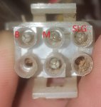
I labeled the connections from the key switch harness to the harness pictured above. bertsmobile1 you mentioned connecting the rectifier to the A on the key switch. Can I connect to the B wire in this harness per StarTech's suggestion? It currently does not have a matching connection in the mating connector. Would connecting to the B be considered wired correctly?
Main Harness End Front.jpg
 

bertsmobile1

Lawn Royalty
Joined
Nov 29, 2014
Threads
65
Messages
24,995
It depends upon the rectifier you have and weather it has diodes to prevent the battery back feeding into the alternator & turning it into a very bad electric motor when the engine is turned off.
 
Last edited:

CubCadet1045

Forum Newbie
Joined
May 3, 2020
Threads
1
Messages
4
My regulator came a day late. I got it connected last night. All seems to be working. I mowed the yard and it started right back up afterward. Battery was still reading 12.2V when I was done.

Thank you all for the help.
 
Top