Lawn Boy 5239g, no spark no matter what I try!

peteclark3

Member
Joined
Jan 1, 2012
Threads
15
Messages
47
I need instructions like you'd explain to a 4 year old... this is my multimeter (it's similar to this)..

http://www.tennesseequipment.com/East-Cost-/Maine-/Agencies-/Craftsman-multimeter-82362-pix.jpg

Instructions like.. touch the red here, touch the black there, and if you see X on the dial, you've got a problem.

I'm a software developer and understand that instructions like this might not be possible, but if it is, then it would definitely help!

Thank you all again for your patience!
:confused2:
 

Two-Stroke

Lawn Addict
Joined
May 7, 2010
Threads
23
Messages
1,594
1) Set the mutimeter to measure resistance (ohms).

2) Put the black wire onto the grounded side of the points. The red wire goes onto the other side.

3) When the points are open, there should be significant resistance shown on the meter. When the points are closed, there should be no resistance shown on the meter (confirming that the points work.)
 

gary lee

Member
Joined
Nov 18, 2011
Threads
13
Messages
32
Hey buddy how was your luck today?
 

Two-Stroke

Lawn Addict
Joined
May 7, 2010
Threads
23
Messages
1,594
Might have found something.. If I am reading the meter right I might have resistance when the points are closed too. I made a video, hopefully it will be easier to help me with this!

5239g won't spark - YouTube

I watched the video but I couldn't tell for sure where you were putting the red wire. The black wire was grounded -- right?

If you have any resistance when the points are closed that's a big problem. Are the points actually making contact? Could there be some dirt or other insulating stuff between them?
 

peteclark3

Member
Joined
Jan 1, 2012
Threads
15
Messages
47
When I re tested, it seemed like I have no resistance no matter if the points are open or closed.

What should I touch the black wire to, to ground it?

And where should I actually be touching the red wire to?

Pete
 

Two-Stroke

Lawn Addict
Joined
May 7, 2010
Threads
23
Messages
1,594
When I re tested, it seemed like I have no resistance no matter if the points are open or closed.

What should I touch the black wire to, to ground it?

And where should I actually be touching the red wire to?

Pete

The black wire could be attached to any metal part of the engine -- you could hook it on with an alligator clip if you have one. The side of the points that does not move when the engine turns is the grounded side.

The red wire goes onto the side of the points where spring connecting the condenser is attached (the side of the points that moves) -- that wire is part of the primary circuit.

If you have no resistance then there may be a short in the primary circuit.
 

gary lee

Member
Joined
Nov 18, 2011
Threads
13
Messages
32
You to remove your advane timing cam see better what you are doing.
 

peteclark3

Member
Joined
Jan 1, 2012
Threads
15
Messages
47
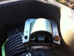
Darn, I thought I had it. To check for a short to ground with the points open, I disconnected the two wires and the points spring from the condenser. The points spring and the wire to the switch didn't have a short to ground, but the wire to the coil did. So I figured maybe it was the white short wire (in the picture) coming out of the coil being connected to one of the screws holding the coil down causing the problem. The old coil (I just got this new one) had the short wire like this, when it was running fine, so I just did the same thing with this new one. Once I disconnected the wire from the screw holding down the coil (as in the picture), I no longer had a short to ground when the points were open. This was what I thought was the "a ha!" moment. Still, once I reassembled everything (for now I just wrapped elec tape around the contact on the short wire), and cranked it, I got no spark.

Now I gotta go tell my son; he came in to watch mower vides on youtube.

Sorry about all this guys but I really appreciate your help! What can I do next? Or, did I do everything totally wrong above?

Pete:confused2:
 

Attachments

  • photo (2).jpg
    photo (2).jpg
    107.5 KB · Views: 8

Eugbug

Member
Joined
Jan 8, 2012
Threads
9
Messages
20
The circuit diagram below is for an ignition system which uses points (non electronic or CDI).
When the current through the magneto primary is at its max, the points open, the magnetic field collapses and you get a high voltage pulse from the secondary which produces the spark at the plug.
You have replaced the condenser(capacitor) and magneto so the chances are these parts are OK.
Check everything is grounded ok. The capacitor is grounded by the clip which holds it. The primary and secondary of the magneto are grounded by the lead coming from the coil in your photo which goes to the left mounting screw for the magneto. One side of the points should be grounded also.
Check the kill switch isn't shorting everything out. From what I can see in the photo, the connecting wire to these is probably the lead coming from the capacitor and disappearing down into the hole. One end of the kill switch is grounded.
As all the other posters suggest, measure the resistance across the points. This should be low and become lower as the points close. It is possible the points aren't adjusted properly and not even closing properly. Often the position of the capacitor is adjusted to give the correct points gap and then the spring on the points properly closed.
 

Attachments

  • ignitioncircuit.jpg
    ignitioncircuit.jpg
    51.6 KB · Views: 9
Last edited:
Top