You are using an out of date browser. It may not display this or other websites correctly.
You should upgrade or use an alternative browser.
You should upgrade or use an alternative browser.
John Deere 116 fails to charge battery
- Thread starter Mtn.Mike
- Start date
More options
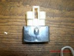
Export threadThat test assumes that the diodes are in a wire. In this case they are in the module which has four pins. I need to know which pins to check such as pin 2 to pin 4. If they were in line this would be easy but they aren't.
Also the 116 has no light circuit since it has no lights so I can't go by that. The module is $45 and maybe it would be just as easy to buy it and hope for the best.
Mike
Also the 116 has no light circuit since it has no lights so I can't go by that. The module is $45 and maybe it would be just as easy to buy it and hope for the best.
Mike
According to the model number you posted and the description you gave of the wires coming from the stator, you unit should not have a voltage regulator. I am at a lose as to what to say or tell you what to do. Can you post any pictures of the components we have been talking about? Also, can you post the exact model number of the tractor?
PJ
Well-Known Member
- Joined
- Mar 18, 2012
- Threads
- 4
- Messages
- 176
Mtn.Mike said:Well I put the new battery in and no change. The electrical system still doesn't charge the battery. I checked the output of the black (from stator) to green to red wire and it was between 15.8 and 16 volts AC.
I will check the red wire going into the module to see if it's the same.
If so would that indicate that the diodes in the module are bad since it appears that there is no DC voltage from there to the battery.
My understanding is the module converts the AC to DC which charges the battery. Is this right?
I will update as to my progress.
Mike :confused2:
Yes correct this module consist from a set of diodes and if one of the diodes burns the unit will not charge your system or gives DC
Sent from my iPad using LMF
You have to remember that these charging systems are AC voltage. A diode actually synthisizes DC voltage because it only allows currant to flow in one direction. Many times you will have a new battery and it keeps going dead. This is usually due to a bad diode because while it "WILL" charge, but when you shut it off, the bad diode is no longer allowing the currant to flow only one direction, so with engine off, the currant flows "FROM" the battery back to the alternator (like a motor) therefore draining the battery. B & S uses 2 different types of diodes. One is a one wire inline usially red and appears like a bulge in the wire. The other is a 3 or 4 wire module encased in epoxy. This is also a regulator. With a low battery it will allow full charging capacity of the alternator, but as the battery builds up charge, it lowers the output as to not overcharge the battery
Can you post a picture of the stator. You said that you have wires cut and going nowhere and weird splices. I am wondering if someone changed the stator and tried to use the wrong voltage regulator/module. Just a thought as I said, this one has me really questioning my knowledge.
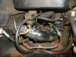
I put the flywheel back on so no pics of the stator. I can show a pic of the single wire coming out of the stator. It started out as a black wire, then someone used a shrink tube and connected the black wire to the green wire I talked about previously. Then the green wire was connected via a spade connector, to the red wire which goes from the engine to the module previously shown.
I have enclosed a pic of the green wire to red wire via the spade connector.

I have enclosed a pic of the green wire to red wire via the spade connector.


