LarryJohnson
Well-Known Member
I'd check voltage on both of them,
I'm getting 34v ac on the yellow wire coming from the engine, and 8.3v dc on red wire coming out of the new VR. Should it be getting 12v dc output or higher.
Last edited:

I'd check voltage on both of them,

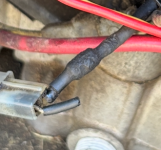
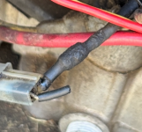
the diode is either not needed or is in the wrong

Yes. The regulator has built in diodes that take the place in the wire. If you want you can disconnect the red connector at the VR, and run a wire directly that connector to the + battery connector and with the engine running see if the battery now is charging.So there's a diode under the shrink wrap? OK, should it just be cut out and wires connected back together.
And I will move wires apart.
Yes. Thanks.Now we're getting somewhere!
the diode will prevent this from happening
Now we're getting somewhere!
The regulator has built in diodes
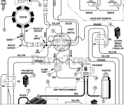
The engine that originally came on that mower had the 3/5 dual circuit non regulated charging system. The current engine is a 9 amp regulated system. So original wiring diagram for the mower will not be accurate for this application. And the fuse should be located in the area of the battery in most cases. Some times is taped over on the side of the wiring loom, sometimes is clipped to a frame piece. Sometimes is just loose hanging.
The engine that originally came on that mower had the 3/5 dual circuit non regulated charging system. The current engine is a 9 amp regulated system. So original wiring diagram for the mower will not be accurate for this application. And the fuse should be located in the area of the battery in most cases. Some times is taped over on the side of the wiring loom, sometimes is clipped to a frame piece. Sometimes is just loose hanging.