You are using an out of date browser. It may not display this or other websites correctly.
You should upgrade or use an alternative browser.
You should upgrade or use an alternative browser.
Export thread
Defective ignition switch?
#1
T
tkos115
T
tkos115
Well, to try and make a long story a little shorter I have a Murray riding mower from 2003. It has a Briggs and Stratton engine on it. Water got into the original switch and caused it to lock up. I put a new ignition switch in it but I never got around to testing it because the battery was dead and it was at a family members house. So it sat under a tarp for about 3 months until they decided they wanted me to fix it up. The problem I'm having is when I crank it, it cranks over fine but I don't get a spark until I let off the crank position and the spark comes back and it will fire. Everything else works fine, lights, charging system, safety switches etc. Now when I unplug a separate prong from that back of the switch that has 2 black wires crimped into 1 pin it will get a spark when cranking and run fine. If I keep this prong unplugged and turn it off it will sputter and spit then die out. (Like the coil isn't getting a good ground to kill the spark). The lights and charging system still work fine when that prong is unplugged. From what I can see for those two black wires on the prong are that one wire goes to the lights, and the other is just a ground that goes to the body.
When I do a continuity test with one test lead on the battery ground, and the other on the backside of the prong that goes to the ignition coil I get these readings..
Key in off position: 0.2 ohms (Normal ground reading)
Key in run position: 1.2ohms
Key in run position with lights on: 1.2ohms
Key in crank position: 0.7ohms
Separate prong unplugged in crank position: 1.2ohms
Does this sound like it's a defective switch that I got? It is a 7 prong switch. Proir to this, I don't believe there were any starting issues like this, but it sat for quiet awhile and wasn't used much.
I would attach some pics but no matter what I do it keeps saying the file size is too large. 1.5mb?
Below is the link to the parts lookup with all the mower info and wiring harness diagram.

 www.partstree.com
Thanks for your time and help all!
When I do a continuity test with one test lead on the battery ground, and the other on the backside of the prong that goes to the ignition coil I get these readings..
Key in off position: 0.2 ohms (Normal ground reading)
Key in run position: 1.2ohms
Key in run position with lights on: 1.2ohms
Key in crank position: 0.7ohms
Separate prong unplugged in crank position: 1.2ohms
Does this sound like it's a defective switch that I got? It is a 7 prong switch. Proir to this, I don't believe there were any starting issues like this, but it sat for quiet awhile and wasn't used much.
I would attach some pics but no matter what I do it keeps saying the file size is too large. 1.5mb?
Below is the link to the parts lookup with all the mower info and wiring harness diagram.

PartsTree - Home of OEM Parts for Outdoor Power Equipment
We are committed to providing you with the largest selection of OEM parts from the best brands, the best diagrams and part search tools anywhere.
 www.partstree.com
Thanks for your time and help all!
#2
B
bertsmobile1
B
bertsmobile1
Basically you got the wrong switch
On top of that you are suffering the calculator disease reading numbers that are most likely wrong and thinking they mean something
Pull the plug and the switch out.
On the back of the switch will be letters like shown here
Usually B G M S A L but may be others
They mean exactly what you think
Battery Ground Magneto Start Alternator Lights
B + S = Cranks
M + G = Stops
B + A = recharges & powers carb solenoid
Work out which wires go where
Get a thin screwdriver or grind down a .040" feeler to depress the barbs so you can pull the terminals out of the plug
hook them direct to the switch where you think they should go
Remove the kill wire from the coil and hook up a meter, test light whatever floats our boat to check that it never gets voltage at any key position
Hook the kill wire up & fire up the engine.
Once happy put the terminals back into the plug and refit the switch.
On some switches with metal bodies that go into metal on the mower the ground wire is not ground to the switch but takes ground from the switch body .
Cant be any more specific without knowing model number of the mower so we can look up the schematic and the actual switch make & number.
#3

Richie F
The wiring diagram in the parts break down is 5 pin.
Why did you buy a 7 pin switch ?
Or do you mean the original switch is a 7 pin ?

 www.partstree.com
Richie F
Does this sound like it's a defective switch that I got? It is a 7 prong switch. Proir to this, I don't believe there were any starting issues like this, but it sat for quiet awhile and wasn't used much.
The wiring diagram in the parts break down is 5 pin.
Why did you buy a 7 pin switch ?
Or do you mean the original switch is a 7 pin ?

PartsTree - Home of OEM Parts for Outdoor Power Equipment
We are committed to providing you with the largest selection of OEM parts from the best brands, the best diagrams and part search tools anywhere.
 www.partstree.com
#4
T
tkos115
T
tkos115
The part number listed seems to goto a 7 pin switch which is what was in it and what I got as a replacement. Might just be a generic picture on the site.
#5

StarTech
StarTech
Hope the OP has the right model number linked.
Richie better yourself a new pair of glasses. Even poor diagram shows 7 terminals. but here is a clearer diagram.
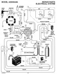
IPL say it is PN 092556 superseding to 092556MA.
Pin Out

Make and Break
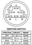
PIN 7 = B. Battery
PIN 6 = G. Ground
PIN 5 = S. Starter
PIN 4 = M. Magneto
PIN 3 = AC from alternator for lighting. Probably A
PIN 2 = L. DC from alternator Also powers after fire solenoid when switch is run and start position when engine not running.
PIN 1 = Lights. Probably Y
PIN 1 and 3 is A and Y and can be connected either way.
Now if the engine is sputtering to stop the with G disconnected the alternator may not be working and you are just shutting using the after fire solenoid.
Richie better yourself a new pair of glasses. Even poor diagram shows 7 terminals. but here is a clearer diagram.

IPL say it is PN 092556 superseding to 092556MA.
Pin Out

Make and Break

PIN 7 = B. Battery
PIN 6 = G. Ground
PIN 5 = S. Starter
PIN 4 = M. Magneto
PIN 3 = AC from alternator for lighting. Probably A
PIN 2 = L. DC from alternator Also powers after fire solenoid when switch is run and start position when engine not running.
PIN 1 = Lights. Probably Y
PIN 1 and 3 is A and Y and can be connected either way.
Now if the engine is sputtering to stop the with G disconnected the alternator may not be working and you are just shutting using the after fire solenoid.
#8

StarTech
StarTech
Heck I having to wear two pairs at the same time now myself. Eye Doctor cant get the prescriptions right. Made a pair for seeing up close but no where near right, instead I need a pair +125 over my regular -350 glasses to see the computer screen clearly. So I can understand somewhat vision problems. Just got remember the separator tube must be working too. 
#9
T
tkos115
T
tkos115
Thanks for your input everyone, I'll be going through doing some more testing in the next day or two now that I have more info. I'm fairly certain that it's a bad switch but I want to make sure before I throw parts at it.
It sounds like since I'm getting a ground to the coil when it's in the crank position there is a switch issue. I couldn't find any pinched or bare wires anywhere.
It sounds like since I'm getting a ground to the coil when it's in the crank position there is a switch issue. I couldn't find any pinched or bare wires anywhere.
#10
S
slomo

slomo
S
slomo
"Calculator disease". Got to love this guy LOLBasically you got the wrong switch
On top of that you are suffering the calculator disease reading numbers that are most likely wrong and thinking they mean something
Pull the plug and the switch out.
On the back of the switch will be letters like shown here
Usually B G M S A L but may be others
They mean exactly what you think
Battery Ground Magneto Start Alternator Lights
B + S = Cranks
M + G = Stops
B + A = recharges & powers carb solenoid
Work out which wires go where
Get a thin screwdriver or grind down a .040" feeler to depress the barbs so you can pull the terminals out of the plug
hook them direct to the switch where you think they should go
Remove the kill wire from the coil and hook up a meter, test light whatever floats our boat to check that it never gets voltage at any key position
Hook the kill wire up & fire up the engine.
Once happy put the terminals back into the plug and refit the switch.
On some switches with metal bodies that go into metal on the mower the ground wire is not ground to the switch but takes ground from the switch body .
Cant be any more specific without knowing model number of the mower so we can look up the schematic and the actual switch make & number.
slomo
#11
B
bertsmobile1
It is a bigger problem than many would think
Those over 60 were taught why and roughed the numbers because the absolute numerical value is not important .
Those under 60 worry about the difference between 1.2Ω and 1.3Ω which in many cases is the pressure on the end of the probe
Those under 40 can not understand why the old one that was 1.27016321 Ω did not work when the specs said 1.2 Ω
Or the one that floored me ,
"The switch you sold me is defective because I get a different ohm reading between the terminals ever time I turn it. "
B
bertsmobile1
"Calculator disease". Got to love this guy LOL
slomo
It is a bigger problem than many would think
Those over 60 were taught why and roughed the numbers because the absolute numerical value is not important .
Those under 60 worry about the difference between 1.2Ω and 1.3Ω which in many cases is the pressure on the end of the probe
Those under 40 can not understand why the old one that was 1.27016321 Ω did not work when the specs said 1.2 Ω
Or the one that floored me ,
"The switch you sold me is defective because I get a different ohm reading between the terminals ever time I turn it. "
#12
T
Telesis
T
Telesis
I too had to laugh at 'calculator disease'! The form of it I witness these days is when someone 'fat-fingers' the buttons and is confident in whatever number is displayed, not thinking at all about how reasonable the answer is, and will defend it "because the calculator says so, it's gotta be right"! I'm 62 and mine was the last engineering class at my university to be taught how to use a slide rule (or slipstick!). 'Slide rule disease' was putting the decimal point in the wrong spot lol!
#13

StarTech
StarTech
Believe it or not calculators can add wrong sometimes. I know as I had to change out nearly 200 cpu chips in the Victor 600 series calculators back in the early '80's. And Victor had the same attitude that it was impossible for them to do it. Several 100 of us techs proved them wrong.
As ohms reading; unless, you got a milliohms meter that can be zerod out even the leads can cause reading differences. In the small engine world close is usually good enough until EFI get fully incorporated then these tiny variances will drive the CPU crazy. Just depends how tightly they are programmed.
As ohms reading; unless, you got a milliohms meter that can be zerod out even the leads can cause reading differences. In the small engine world close is usually good enough until EFI get fully incorporated then these tiny variances will drive the CPU crazy. Just depends how tightly they are programmed.
#14
B
bertsmobile1
B
bertsmobile1
Meters are the opposite to every other tool I use.
All of the on site service tools are good quality domestic grade so when I loose one on site, no great financial loss .
The Stahlwile , Sidchromes & Dufors stay in the workshop .
In the workshop I use test leads with either a buzzer or lamp on
In the field I use expensive looking multi ,meters but just ignore the numbers .
#15
T
tkos115
T
tkos115
So, as an update. I went through and verified all the pins were correct, (which they were). I went through each wire to make sure that nothing was shorted out, and made sure that all the safety switches were good, (they also were). I bought a new quality switch from a local suppler and installed it. Well.... still no spark when cranking over.. At this point I'm about to pull my hair out as nothing is making any sense. After fiddling around with some stuff and watching for a spark as I crank it I noticed something.. If I let off the switch when cranking it just a tiny bit the spark comes back, if I turn it all the way to the stop on the switch it goes away again. For the heck of it, I did it with the old new replacement and it does the same thing. Anyone else had this issue with new switches? So far two brand new switches are doing the same thing. I will see about swapping the newest one out for a replacement as it seems to be defective as well. But at least it seems it's a switch issue not a wiring problem.
#16
B
bertsmobile1
B
bertsmobile1
Take the blower housing off and pull the kill wire off
Remove the spark plug and check that you get continuity too ground in the off position and open circuit to ground in all other positions including when cranking .
If this is not the case then either the kill wire is shorted to ground some where or a switch is shorting it to ground.
As for the latter the most likely suspect is the PTO or brake switch .
Like Dorothy following the yellow brick road, you need to follow the yellow wire
In both the cranking and the running positions the yellow wire should always be open circuit to ground
The yellow wire goes to ground to kill the magneto spark
The safety switches are primative sliding contact switchs and regularly go bad
The easiest way to test them is to bypass them by unpluging then bridging the other pair of wires ( orange ones ) which are the cranking circuit
If the mower fires up as it should then plug them back in one at a time to find the culprit .
Just remember the culprit can be a bad switch or bad wires between switches .
With all of the yellow wires unpluged there should be no continuity to ground at any plug
If there is then there is a short in that section of wire.
#17
T
tkos115
I do get a ground in the off position with the wire pulled when I check it. It remains an open circuit in all key positions until I hold it in the crank position. If I back the key turn off maybe .20in the spark comes back and works fine. If I turn the key that .20in again when cranking it goes away and the wire is grounded again. It seems like it's the ignition switch, but it does that on both switches so maybe they are both defective? It may be even less than .20in that I have to let the key turn back from full crank but it's a very tiny amount.
T
tkos115
Take the blower housing off and pull the kill wire off
Remove the spark plug and check that you get continuity too ground in the off position and open circuit to ground in all other positions including when cranking .
If this is not the case then either the kill wire is shorted to ground some where or a switch is shorting it to ground.
As for the latter the most likely suspect is the PTO or brake switch .
Like Dorothy following the yellow brick road, you need to follow the yellow wire
In both the cranking and the running positions the yellow wire should always be open circuit to ground
The yellow wire goes to ground to kill the magneto spark
The safety switches are primative sliding contact switchs and regularly go bad
The easiest way to test them is to bypass them by unpluging then bridging the other pair of wires ( orange ones ) which are the cranking circuit
If the mower fires up as it should then plug them back in one at a time to find the culprit .
Just remember the culprit can be a bad switch or bad wires between switches .
With all of the yellow wires unpluged there should be no continuity to ground at any plug
If there is then there is a short in that section of wire.
I do get a ground in the off position with the wire pulled when I check it. It remains an open circuit in all key positions until I hold it in the crank position. If I back the key turn off maybe .20in the spark comes back and works fine. If I turn the key that .20in again when cranking it goes away and the wire is grounded again. It seems like it's the ignition switch, but it does that on both switches so maybe they are both defective? It may be even less than .20in that I have to let the key turn back from full crank but it's a very tiny amount.
#18
B
bertsmobile1
B
bertsmobile1
Congratulations now you have made my brain hurt to.
First question
Have your tried it with the safety switches jumped on the orange & yellow open like I asked ?
Second is the seat switch a simple 2 pin switch as shown in the diagram ?
Third question is there a relay installed on the yellow wire any where ?
First question
Have your tried it with the safety switches jumped on the orange & yellow open like I asked ?
Second is the seat switch a simple 2 pin switch as shown in the diagram ?
Third question is there a relay installed on the yellow wire any where ?
#19
T
tkos115
T
tkos115
Yeah, I did jump the switches and the seat switch is just a two wire. I didn't find any relays anywhere. Just a 15amp fuse for the main power going to the switch which is good. (Red wire)
#20

StarTech
It appears that you don't understand the kill circuit operation. In the yellow path. The brake switch must be open (Switch depressed), The PTO will be in open position in disengaged position. The seat switch must be open (switch depressed or operator on seat). Note: The parts list does it being wired the same as the brake/clutch switch which is incorrect. It contact positions is drawn backwards. The seat switch is common to both the brake switch and PTO circuit magneto kill circuit.
Anyways what you are describing is defective ignition switches or the you have the wrong ones. Are you trying to after market or oem switches? It should never ground the magneto in start position. I do know that Oregon 33-383 is the same switch as the Murray 92556 (superseded to Briggs 092556MA). I have tested the in house new Oregon switch here and it does not short out the magneto in start position.
StarTech
Just note here the starter solenoid used is a relay (contactor). Just depends industry you familiar with.Yeah, I did jump the switches and the seat switch is just a two wire. I didn't find any relays anywhere. Just a 15amp fuse for the main power going to the switch which is good. (Red wire)
It appears that you don't understand the kill circuit operation. In the yellow path. The brake switch must be open (Switch depressed), The PTO will be in open position in disengaged position. The seat switch must be open (switch depressed or operator on seat). Note: The parts list does it being wired the same as the brake/clutch switch which is incorrect. It contact positions is drawn backwards. The seat switch is common to both the brake switch and PTO circuit magneto kill circuit.
Anyways what you are describing is defective ignition switches or the you have the wrong ones. Are you trying to after market or oem switches? It should never ground the magneto in start position. I do know that Oregon 33-383 is the same switch as the Murray 92556 (superseded to Briggs 092556MA). I have tested the in house new Oregon switch here and it does not short out the magneto in start position.
#21
B
bertsmobile1
There are some Toros ( I think ) that use a common relay for cranking and for killing which is why I asked about a relay .
I had a similar fault because this relay had failed and it caught me out because both trigger connections were used and they switched functions once the cranking stopped.
B
bertsmobile1
Just note here the starter solenoid used is a relay (contactor). Just depends industry you familiar with.
It appears that you don't understand the kill circuit operation. In the yellow path. The brake switch must be open (Switch depressed), The PTO will be in open position in disengaged position. The seat switch must be open (switch depressed or operator on seat). Note: The parts list does it being wired the same as the brake/clutch switch which is incorrect. It contact positions is drawn backwards. The seat switch is common to both the brake switch and PTO circuit magneto kill circuit.
Anyways what you are describing is defective ignition switches or the you have the wrong ones. Are you trying to after market or oem switches? It should never ground the magneto in start position. I do know that Oregon 33-383 is the same switch as the Murray 92556 (superseded to Briggs 092556MA). I have tested the in house new Oregon switch here and it does not short out the magneto in start position.
There are some Toros ( I think ) that use a common relay for cranking and for killing which is why I asked about a relay .
I had a similar fault because this relay had failed and it caught me out because both trigger connections were used and they switched functions once the cranking stopped.
#22
T
tkos115
T
tkos115
So just an update, I was able to finally fix the issue with this mower. It turned out to be an ignition switch issue. After putting the 4th switch in it, the problem went away and it has been working fine. The first brand I went with for the first two switches was Stens, then the last two I went with the Briggs made 092556MA. All the switches were looked up and were listed as a replacement for the 092556MA part number. I have never had such bad luck with defective parts like this but im glad it's finally done..
#23

StarTech
StarTech
I wouldn't think I have problem with Briggs OEM fuel solenoids either but I had 6 in a row that would not retract; unless, they were bumped.
So yes there can be batches of defective items.
So yes there can be batches of defective items.
#24
B
bertsmobile1
This is exactly why I kept on recommending using patch cords to bypass switches and if necessary bypass wiring between switches .
Stens stand by their products when bought from an authorised dealer and down here have always been very grateful when I found a defective product so send the duff ones back for a refund.
Glad you got it beaten feel good dosen't it.
B
bertsmobile1
So just an update, I was able to finally fix the issue with this mower. It turned out to be an ignition switch issue. After putting the 4th switch in it, the problem went away and it has been working fine. The first brand I went with for the first two switches was Stens, then the last two I went with the Briggs made 092556MA. All the switches were looked up and were listed as a replacement for the 092556MA part number. I have never had such bad luck with defective parts like this but im glad it's finally done..
This is exactly why I kept on recommending using patch cords to bypass switches and if necessary bypass wiring between switches .
Stens stand by their products when bought from an authorised dealer and down here have always been very grateful when I found a defective product so send the duff ones back for a refund.
Glad you got it beaten feel good dosen't it.
#25
S
ShaneZampire
S
ShaneZampire
I thought I would share since this page is now the top result when you google this problem. Maybe others will chime in and we can all help each other.
I have 5 Murray wide body mowers. All around 2000-ish models. 4 are in great working condition. I just like them so I pick them up when I find a good deal and restore them. All have the 7 terminal ignition switches. I am sure some have been replaced over the years with OEM and aftermarket but, they all work as they should and as intended.
So 4 weeks ago I picked up my 5th one. Was ok for a two decade old mower but needed paint, and a going through. I asked the guy what all was wrong with it and he said the biggest problem was you had to hold the key in the start position for like 30 seconds, then let off and it would start. He said he replaced the solenoid, plugs, new carb, key switch last season, and it didn't change a thing so he just lived with it. He said had to be the coil. So 3 weeks ago as I was going through it, checking all wires, switches, diodes, etc. I had the spark plugs out and noticed they only fired once I let off the key switch and motor was winding down. o0 So I took the switch and checked it out. Sure enough, it was grounding out to "M" in the start position. I knew he said it was doing same thing before he put on a new switch last year. What is the odds? So I checked and double checked ignition switch part numbers, wiring diagram, and ignition switch position contacts. All was correct other than the ignition switch was making an extra contact it should not be which is engine kill and engine start at same time.
So I order another aftermarket switch off Amazon. Two days later it arrives and I just throw it on. Same thing! No way! Check the switch and it is same way. I immediately come in, request a refund, and order another brand. Two days later I receive that switch. Same thing, Start makes contact with B+L+S M+G I walk into the house, request a refund and order a Stens switch. 3 days later I receive another defective switch. I am now on my 4th switch and will be ordering an Oregon 33-383 I seen someone here mention. If this one is defective, I guess I will track down some NOS OEM switches. But when they say its a direct replacement for Murray - 92556, Murray - 092556MA, either they are just flat out wrong or we have a mass batch of defective switches.
I have been reading and researching this for 3 weeks now and this problem goes back years from looking at the dates on some the reviews and posts. And its not just one brand. They all messed up or there is just one company making the same switch and just labeling it who's ever brand.
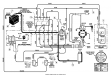
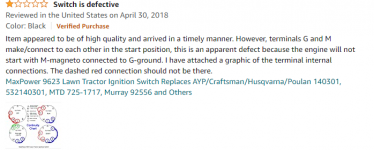
Below is the ignition switch contacts and wiring for the 92556 switch and also a few random reviews from different brand switches that are "suppose to be" exact replacements for the common standard 7 terminal Murray and other mowers of the 2000 era.



#26
B
bertsmobile1
B
bertsmobile1
IS the connections B+L+S+M according to the letters on the back of the switch or the actual wires in the plug ?
If that was the actual switching then it is putting voltage onto the magneto and that will kill the trigger chip the very second that contact is made thus destroying it
If that was the actual switching then it is putting voltage onto the magneto and that will kill the trigger chip the very second that contact is made thus destroying it
#27
S
ShaneZampire
It's actually B+L+S AND M+G terminals making contact in the start position. Its almost like the switches are in the start position and off position at the same time other than the "L" does not make contact with M+G in the "Start" position as it does in the "Off" position. The terminals are lettered on the actual switch just as in the picture above.
I got side tracked on another project so this one got put off for a little while. Right after the above post, I did have another switch come in I had ordered off eBay I forgot about. It is the same way. No brand. It just came in a little white box. So I now have 3 defective switches on hand and the 5th I have tried and tested bad.
Also shortly after the above post, I had plans of trying the Oregon one and Tractor Supply has a MTD 7 terminal one in stock. I was going to ask the manager could I test it right there in the store. I got around to neither. I did find a NOS one on eBay for the same price as all the others so I ordered it as an intended spare. It just came in about 2 hours ago. I just tested, double, and triple tested it. In the "Off" position, only M+G+L make contact and in "Start" position, only B+L+S make contact. Below is the exact one that I just now received.
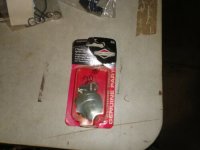
S
ShaneZampire
bertsmobile1:
It's actually B+L+S AND M+G terminals making contact in the start position. Its almost like the switches are in the start position and off position at the same time other than the "L" does not make contact with M+G in the "Start" position as it does in the "Off" position. The terminals are lettered on the actual switch just as in the picture above.
I got side tracked on another project so this one got put off for a little while. Right after the above post, I did have another switch come in I had ordered off eBay I forgot about. It is the same way. No brand. It just came in a little white box. So I now have 3 defective switches on hand and the 5th I have tried and tested bad.
Also shortly after the above post, I had plans of trying the Oregon one and Tractor Supply has a MTD 7 terminal one in stock. I was going to ask the manager could I test it right there in the store. I got around to neither. I did find a NOS one on eBay for the same price as all the others so I ordered it as an intended spare. It just came in about 2 hours ago. I just tested, double, and triple tested it. In the "Off" position, only M+G+L make contact and in "Start" position, only B+L+S make contact. Below is the exact one that I just now received.

#28
B
bertsmobile1
B
bertsmobile1
Does not make sense to have a switch with B+L+S & M+G at the same time unless the mower uses a NC relay on the magneto kill wire.
M+G+L uses the alternator as a brake to stop the engine faster .
As you have worked out by now there are a lot of variations and the number of terminals alone is not a good enough description of a switch.
Down stairs I have at least 2 different 7 pin switches .
The box of good used switches has at least 20 different switches , many of which will plug in but not work on a particular mower.
The other sneaky problem is the Ground wire to the switch is often just screwed into the dash and quite a bad ground .
#29
S
ShaneZampire
Also Update: I installed the NOS OEM one today. Turned the key and it fired right up after about turning over 3-5 times. It was nice not having to wind the motor for a few seconds, let off, and hope this is the time it starts. This one has the 19.5hp B&S Twin engine so the fuel pump is steady pumping gas into the carb. when turning over. With the defective switches, you better wind it up just right and let off or you was for sure going to flood the crap out of it.
If time allows and I don't forget, I want to take one of these defective (or switches purposely made to make extra contacts) apart and just see what's going on inside. Take some pictures and share. When I Googled this problem, this thread was the #1 result. It helped me. I know there are others out there from the 3 weeks of poking around, reading so many reviews, other forums, and other places with people the same problem.
S
ShaneZampire
Yea, the MTD one at Tractor Supply has no mention of replacement for 92556, 092556MA. I was just hoping it would make the correct contacts I needed and was looking for. It just says "MTD OEM-725-1717 Ignition Switch. Simple to install, the riding mower ignition switch fits garden tractors made in 2002 and prior." All the others I had bought, tried, and tested actually said 92556, 092556MA replacement which they were not or all defective. Also to note is the 7 terminals are arranged like a Christmas tree. 1 then 2 then 3 on bottom row. (6 terminals) Then the 7th (ground) is off to the side and just a wire with a space connector slides onto that terminal. The plastic molded wire plug will only fit the correct arranged terminals.As you have worked out by now there are a lot of variations and the number of terminals alone is not a good enough description of a switch.
Down stairs I have at least 2 different 7 pin switches .
Also Update: I installed the NOS OEM one today. Turned the key and it fired right up after about turning over 3-5 times. It was nice not having to wind the motor for a few seconds, let off, and hope this is the time it starts. This one has the 19.5hp B&S Twin engine so the fuel pump is steady pumping gas into the carb. when turning over. With the defective switches, you better wind it up just right and let off or you was for sure going to flood the crap out of it.
If time allows and I don't forget, I want to take one of these defective (or switches purposely made to make extra contacts) apart and just see what's going on inside. Take some pictures and share. When I Googled this problem, this thread was the #1 result. It helped me. I know there are others out there from the 3 weeks of poking around, reading so many reviews, other forums, and other places with people the same problem.
#30
S
ShaneZampire
S
ShaneZampire
So I took the switch apart. Here is what I think I see. The contacts are around the outer edge like numbers on a clock. The contact wipers are fan shaped. The inside (center) of the each wiper has a little nipple that can make contact with G or L because them two contacts have copper traces that run inside to the center. The outside is wide enough to catch 2 contacts at a time. Each wiper is 180 of each other (straight across from one another). Each wiper has a spring that presses them down onto the contacts to keep pressure on them. Each wiper's outer wide side is curled up (so it slides smoothly across the contacts)
So when the key is in the "Start" position, one wiper, the outer fan is on B+S and the inside of the wiper is on L. Now the other wiper ... It is almost centered directly over the G contact but little to the M side. It is offset enough that with the spring pressure, with the inside teetering on the inside nipple, and the wide fan part on the raised G contact, it will tilt onto and make contact with the M. It looks like the designers actually put two raised places on the board on each side of the G contact to prevent this maybe?. But this switch I took apart, the raised part between the G and M is not high enough. It looks like it was a tad higher, and with the ends of the wipers curled a little, it may would not make contact.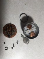
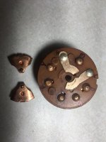
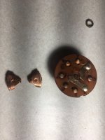
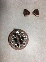
So when the key is in the "Start" position, one wiper, the outer fan is on B+S and the inside of the wiper is on L. Now the other wiper ... It is almost centered directly over the G contact but little to the M side. It is offset enough that with the spring pressure, with the inside teetering on the inside nipple, and the wide fan part on the raised G contact, it will tilt onto and make contact with the M. It looks like the designers actually put two raised places on the board on each side of the G contact to prevent this maybe?. But this switch I took apart, the raised part between the G and M is not high enough. It looks like it was a tad higher, and with the ends of the wipers curled a little, it may would not make contact.


