You are using an out of date browser. It may not display this or other websites correctly.
You should upgrade or use an alternative browser.
You should upgrade or use an alternative browser.
Bobcat/ briggs wiring help!
- Thread starter madman
- Start date
More options
Export threadYes. I probably do not need both. Originally this mower did not have a starter or a battery. Had a mounting spot for a starter. I built a tray for a battery. To much to pull when trying to get it started. Four shoulder surgery's to date...
or a key switch. Just the on off (black ) switchYes. I probably do not need both. Originally this mower did not have a starter or a battery. Had a mounting spot for a starter. I built a tray for a battery. To much to pull when trying to get it started. Four shoulder surgery's to date...
Fish
Lawn Pro
- Joined
- Aug 2, 2013
- Threads
- 11
- Messages
- 5,145
What about the solenoid on the carb?Yes. I probably do not need both. Originally this mower did not have a starter or a battery. Had a mounting spot for a starter. I built a tray for a battery. To much to pull when trying to get it started. Four shoulder surgery's to date...

This machine always had the solenoid on the carb. And I was under the impression that on a single lead wire stator if I had a rectifier and was working correctly that it not only would restrict the back flow from the battery but also convert ac to dc. Is this not correct? But From what I also gather there is no bench test for a rectifier. Only if the machine is already running.What about the solenoid on the carb?
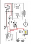
Also there was a reply with two circles around two red leads coming off of the coil. One lead is not being used. That the only wire this guy didn't cut and left the connector on. The other wire i'm assuming is now my hot lead for everything with the exception of the starter. I believe I found a diagram on the briggs site as suggested. I'm going to post it to find out what everyones thoughts are. I'm still in the dark a bit on my pto switch. I understand the concept of normally open and normally closed. Just confused as to which wires go where on the pto switch and at what sequence the power/grounds ect. go through it.
I do not have lights. so I'm assuming a pigtail from the out going wire off of the rectifier to the carb solenoid.
Attachments
- Joined
- Feb 19, 2020
- Threads
- 120
- Messages
- 12,836
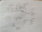
Pin of the PTO switch you have is as (with right side being commons)

If the rectifier is a simple diode it is bench testable. Low resistance forward biased and high resistance reversed biased. If regulator/ rectifier setup then it is only testable in operation, either works or not.
The reason asked which switch your have. Different switches have different modes of contacts in off, run, and start positions. Just looking at physically doesn't show how it works internally.
Supposedly this is the order on the switch. He replaced that as well and just marked on the sides of it the alph pattern. There are no stamped letters on the blades or the housing.Pin of the PTO switch you have is as (with right side being commons)
View attachment 51865
If the rectifier is a simple diode it is bench testable. Low resistance forward biased and high resistance reversed biased. If regulator/ rectifier setup then it is only testable in operation, either works or not.
The reason asked which switch your have. Different switches have different modes of contacts in off, run, and start positions. Just looking at physically doesn't show how it works internally.
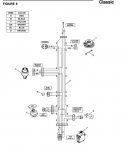
Attachments
And I finally found a schematic which I believe is correct to at least the original wiring of the machine. Think I'm going to go to this guys house and take a pair of linesman plyers to every wire coming out of his power panel.... kidding.Supposedly this is the order on the switch. He replaced that as well and just marked on the sides of it the alph pattern. There are no stamped letters on the blades or the housing.