on these engines the throttle plate should never fully close... if you can, post a picture of the carburetor and the linkage on your mower.So does the choke plate ever close? If so, when?
Thanks everyone for the input so far.

on these engines the throttle plate should never fully close... if you can, post a picture of the carburetor and the linkage on your mower.So does the choke plate ever close? If so, when?
Thanks everyone for the input so far.

No, you take the air filter off and look into the throat of the carb and watch, you should see a pulse of fuel pop up into the throat.I should be able to see a gush of fuel pop up? Where would I see this? can I see it with the air filter on?
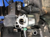
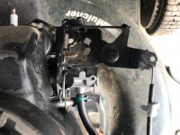
Here are pics., Let me know if you need better, closer etc. Thanks!on these engines the throttle plate should never fully close... if you can, post a picture of the carburetor and the linkage on your mower.


Great diagram and explanations, thanks!All of your throttle linkage appears correct.
What i outlined in red is your throttle shaft and throttle plate (also called a butterfly valve, sometimes) it should sit a wide open (like it is) when the engine is not running, and close down to a little less than half way open when running.
What i outlined in green is your emulsion tube, which the main jet screws into, you should see fuel squirt out of it when you press the primer bulb.
what i circled in purple is the hole for the air impulse into the fuel bowl, which then push fuel out of the main jet.
Here is the back of your airbase/primer assembly.... when you push the bulb, air follows the path i outlined in blue, and comes out the hole i circled in blue, the hole corresponds with the the hole that i circled in purple on the carburetor.
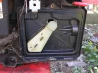
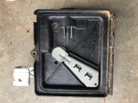
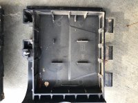
take a picture of the back of it, where the gasket goes.Here are pics of the air filter housing.