ariens no power

ACF

Well-Known Member
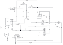
have an ariens ikon 52 model 915223 has no power at key switch, traced all the wiring in according to wiring drawing found no problems, except at the area with fuses. continuity check was good from solenoid to 30 amp fuse, but from there to ignition switch there was nothing. replaced the brake switch no change. the crazy thing the wiring drawing shows a red wire going into and out the 30 amp fuse but this unit has red on one side and purple on the other side, the wiring drawing shows red should be in and out of 30 amp fuse. the 15 amp fuse has red wire going into fuse and purple coming out the drawing shows that purple should be in and out of 15 amp fuse. owner says was running and just stopped and will not start. mower will turn over when solenoid is jumped cross the poles. the owner did some electrical work on mower was told replaced key switch, but not sure if that was all that was done, is there a chance that someone changed the position of the red and purple wires going into the fuse panel. any suggestion would be great
thank you
AC
 
have an ariens ikon 52 model 915223 has no power at key switch, traced all the wiring in according to wiring drawing found no problems, except at the area with fuses. continuity check was good from solenoid to 30 amp fuse, but from there to ignition switch there was nothing. replaced the brake switch no change. the crazy thing the wiring drawing shows a red wire going into and out the 30 amp fuse but this unit has red on one side and purple on the other side, the wiring drawing shows red should be in and out of 30 amp fuse. the 15 amp fuse has red wire going into fuse and purple coming out the drawing shows that purple should be in and out of 15 amp fuse. owner says was running and just stopped and will not start. mower will turn over when solenoid is jumped cross the poles. the owner did some electrical work on mower was told replaced key switch, but not sure if that was all that was done, is there a chance that someone changed the position of the red and purple wires going into the fuse panel. any suggestion would be great
thank you
AC
I have had 4 electrical issues so far this year on no start problems from ignition switch, and have yet to figure them out. I can get them started, just not without running jumper from ignition switch to solenoid trigger momentarily. Therefore I feel your pain and frustration.
 
found the problem the fuses were installed wrong position, owner admitted that he played with the fuses after i told him what i found after doing electrical checks and finding no problems
 
Try a Toro I just done. Checking voltages to ground all show good even at the starter solenoid. The problem is that this mower uses a replay in the ground circuit. That relay in run position operated but in the start position it shuts down. The problem was I was losing the 12V at the grounding relay in the start position which was not the ignition switch.

The problem quite simple to find using the electrical schematic.
 
Engineers for mechanical equipment and the automotive industry have changed their traditional electrical circuit game in recent years. Now it is not unusual to find fuses and relays in the negative circuit of many.

I recently got called to troubleshoot a Massey Ferguson farm tractor. The initial shop tech had a bad habit of throwing parts at problems with no actual diagnostics.

The problem turned out to be a 5A fuse for a main power relay ground. The other problem was it took the shop manager 3 weeks to call me after the situation got desperate and the farmer was screaming at him.

Most people never think to switch their simple test light lead over to battery positive post to verify the circuit negative side.
 
Last edited:
What is irritating me is these stupid line diagrams that some OEM are putting out. I have worked in electronics for 40 yrs and what they now call logic diagrams make a heck a lot more sense to me. On those line diagram I am having to look up each component just find out their internal wiring per say so I follow the wiring from a source to destination.

At least this unit has a logic diagram that I can follow. So much easier to troubleshoot. There is nothing between the fuse holder the B+ terminal other than the wiring. Now depending how you are checking between the fuse holder the ignition could be the problem if the terminals at either end is bad.
 
Back
Top