Pretty sure I did when the engine was replaced... They all tied to one mounting bolt on the back of the engine... But does not hurt to go over them again.Loosen clean and retighten all of the harness grounds starting at the battery.

You are using an out of date browser. It may not display this or other websites correctly.
You should upgrade or use an alternative browser.
You should upgrade or use an alternative browser.
Wiring diagram help.
- Thread starter BrianSki
- Start date
Auto Doc's
Lawn Addict
Look around the chassis carefully, because they often attach one to the metal floor area or engine base.
Does that regulator have the typical 3 wires and then 2 more in the middle of the epoxy? I know some Kawasaki and Kohler engine had that style. On the B&S, the charge light circuit is likely run through a control module with a sense circuit for the charging.
Sometimes, it could just be that the base/low idle is set too low and needs to be adjusted a 1/4 turn so the regulator reads the output of the stator better.
EDIT: I have also had times where I would run a dedicated ground wire to a regulator mounting screw to ensure a proper ground to it.
In any charging circuit the ground is just as important as the positive side but often overlooked.
Does that regulator have the typical 3 wires and then 2 more in the middle of the epoxy? I know some Kawasaki and Kohler engine had that style. On the B&S, the charge light circuit is likely run through a control module with a sense circuit for the charging.
Sometimes, it could just be that the base/low idle is set too low and needs to be adjusted a 1/4 turn so the regulator reads the output of the stator better.
EDIT: I have also had times where I would run a dedicated ground wire to a regulator mounting screw to ensure a proper ground to it.
In any charging circuit the ground is just as important as the positive side but often overlooked.
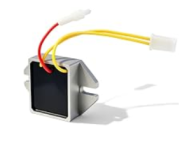
It is the 3 wire regulator. 2 for the stator and one red for charging.Does that regulator have the typical 3 wires and then 2 more in the middle of the epoxy?
I ran the meter to check resistances. Battery to regulator ground had no resistance. (good, direct connection)
I swapped the regulator. I was then getting about 14.3 volts at the battery. Light still on.
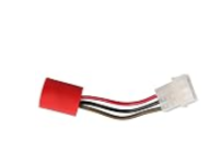
The battery light module has 3 wires, one ground, one positive and one to the light. It had a good ground and good + voltage, same as battery. Pretty sure module is bad. They sell a lot of them on Amazon. $12. Will be here tomorrow.
I was thinking rusted or loose ground screws, but every thing looked good.EDIT: I have also had times where I would run a dedicated ground wire to a regulator mounting screw to ensure a proper ground to it.
In any charging circuit the ground is just as important as the positive side but often overlooked.
Always the strange, it worked before... But everything does before it doesn't.
Auto Doc's
Lawn Addict
Have you ever made pudding and found out the milk was sour? Looks good, but the taste tells another story. LOL