Wiring help please!

Rmstoico

Forum Newbie
Joined
Apr 27, 2013
Threads
1
Messages
5
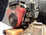
I picked this up cheap in hopes to get it running. The wiring is a nightmare and my first goal is to get the motor running. I am trying to do this by bypassing all of the wiring from the deck, seat bypass, etc...

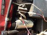
As u see in the pics, the engine is a b&s vanguard 16 hp v twin. The second pic shows only 3 wires coming from the engine, so my guess is if I can correctly apply the correct positive or negative voltage to these and jump the starter I can get it running. The engine turns but does not start when I currently jump the starter.

Can anyone tell me what the yellow, black to red, and red to red wires are for or need to be connected to?
 

Attachments

  • image.jpg
    image.jpg
    295.8 KB · Views: 16
  • image.jpg
    image.jpg
    237 KB · Views: 18

Rmstoico

Forum Newbie
Joined
Apr 27, 2013
Threads
1
Messages
5
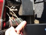
Here is a better pic of the 3 wires (I'm holding them) that I need to figure out
 

Attachments

  • image.jpg
    image.jpg
    229.1 KB · Views: 16

natenkiki2004

Well-Known Member
Joined
Apr 22, 2011
Threads
13
Messages
177
You really should read through the manuals for your engine but I will try to help you out.

http://www.lawnmowerforum.com/attac...14054d1367096263-wiring-help-please-image-jpg
In that picture, you see a soda-pop can sized object. That's the starter. See at the base a large red wire coming off? That is the positive lead that would go through the solenoid to start the engine. Negative is grounded to frame. On the right in that picture, you see a rectangle bolted right next to the starter, that's a rectifier. The yellow wires going back inside the engine go to the alternator. The red wire coming out of the rectifier is to charge the battery. Don't apply any voltage to those, you could fry either the rectifier and/or solenoid and they're not cheap.

http://www.lawnmowerforum.com/attac...14055d1367096820-wiring-help-please-image-jpg
In this picture I am guessing that the wire in the top of your hand (upper red one) is a kill switch for the ignition. I could be wrong so don't sue me :) Another good reason to read the manual. The wire off to the right (yellow?) looks like a ground wire that was added by a previous owner.


I highly recommend going to the Briggs site and picking up the manual for your engine:
http://www.briggsandstratton.com/us/en/support/manuals
Then, go to your equipment manufacturer (looks like MTD) and get a manual for the mower which will include a wiring diagram:
PDF Manual Web Archive
 

Rmstoico

Forum Newbie
Joined
Apr 27, 2013
Threads
1
Messages
5
You really should read through the manuals for your engine but I will try to help you out.

http://www.lawnmowerforum.com/attac...14054d1367096263-wiring-help-please-image-jpg
In that picture, you see a soda-pop can sized object. That's the starter. See at the base a large red wire coming off? That is the positive lead that would go through the solenoid to start the engine. Negative is grounded to frame. On the right in that picture, you see a rectangle bolted right next to the starter, that's a rectifier. The yellow wires going back inside the engine go to the alternator. The red wire coming out of the rectifier is to charge the battery. Don't apply any voltage to those, you could fry either the rectifier and/or solenoid and they're not cheap.

http://www.lawnmowerforum.com/attac...14055d1367096820-wiring-help-please-image-jpg
In this picture I am guessing that the wire in the top of your hand (upper red one) is a kill switch for the ignition. I could be wrong so don't sue me :) Another good reason to read the manual. The wire off to the right (yellow?) looks like a ground wire that was added by a previous owner.


I highly recommend going to the Briggs site and picking up the manual for your engine:
Manuals & Parts
Then, go to your equipment manufacturer (looks like MTD) and get a manual for the mower which will include a wiring diagram:
PDF Manual Web Archive

I think the yellow wire is the kill wire. Although it looks like a ground, it is attached with a piece of plastic between it and the motor, like many other kills are on other motors.

I also think the wire coming from the top of the motor is the alternator wire. The only wire I wonder about is the one going into that square box thing with the 2 yellow wires coming out and going back to the inside of the motor.

I'm surprised nobody here can tell me what wires I need if I were to just get this running as if it were on a bench. Again, I'm bypassing all kills and bypass switches.
 

Rivets

Lawn Royalty
Joined
Mar 11, 2012
Threads
59
Messages
15,307
Well you know more than me, so I'm out of here. Won't get in the way. Bye.
 

natenkiki2004

Well-Known Member
Joined
Apr 22, 2011
Threads
13
Messages
177
I think the yellow wire is the kill wire. Although it looks like a ground, it is attached with a piece of plastic between it and the motor, like many other kills are on other motors.

I also think the wire coming from the top of the motor is the alternator wire. The only wire I wonder about is the one going into that square box thing with the 2 yellow wires coming out and going back to the inside of the motor.

I'm surprised nobody here can tell me what wires I need if I were to just get this running as if it were on a bench. Again, I'm bypassing all kills and bypass switches.


The yellow wire wouldn't make sense to be a kill. Why would a previous owner directly connect the kill switch to a bolt? That would mean you could NEVER start the engine unless you unplugged that wire and then plugged it in to kill it. Who knows though...

The upper wire could also be an alternator wire, but AC only. The box is definitely a rectifier and coming out of it will be DC. The two yellow wires going into it are AC from the alternator.

If you want to run the engine like on a bench, disconnect everything and hook the starter up to a battery. I personally just like to get familiar with a wiring diagram, eliminate multiple connection points by soldering then clean the remaining contacts. Most important to me is a properly working kill switch.
 

Rmstoico

Forum Newbie
Joined
Apr 27, 2013
Threads
1
Messages
5
The yellow wire wouldn't make sense to be a kill. Why would a previous owner directly connect the kill switch to a bolt? That would mean you could NEVER start the engine unless you unplugged that wire and then plugged it in to kill it. Who knows though...

The upper wire could also be an alternator wire, but AC only. The box is definitely a rectifier and coming out of it will be DC. The two yellow wires going into it are AC from the alternator.

If you want to run the engine like on a bench, disconnect everything and hook the starter up to a battery. I personally just like to get familiar with a wiring diagram, eliminate multiple connection points by soldering then clean the remaining contacts. Most important to me is a properly working kill switch.

The yellow wire is a factory connection. The pic sucks but it's not just bolted to the motor. It goes to a bolt that is separated from the metal by a plastic piece. U can tell its not added by someone. A friend of mine has a craftsman where the negative kill looks exactly the same. It's not showing negative on the meter even when I am jumping the starter directly to a battery, so I'm guessing its not malfunctioning anyway. Motor turns will all wires disconnected, just doesn't start. Pulled the plugs and the chamber is not flooded. There is fuel in the lines but I'm not sure if its going thru the carb. Will check that next I guess. Thanks for the help.
 

natenkiki2004

Well-Known Member
Joined
Apr 22, 2011
Threads
13
Messages
177
If that yellow wire is isolated from the shroud, there must be another wire on the other side that goes somewhere (likely to the kill for the ignition then). I've just not seen that on the MTD & Briggs tractors I've worked on. I've seen it on older Tecumseh engines on snowblowers though.

To answer your private message, I thought it would be best to post the information publicly. The rectifier basically takes AC and turns it into DC to charge the battery and run electrical stuff. See page 16 of this PDF for your type of rectifier:
https://dl.dropboxusercontent.com/u...18-46 Riding Mower/alternator_replacement.pdf
Lot of good info in there, talks about shunts, starter amperage and more.

*EDIT* Forgot to answer your question! No, a rectifier or charging circuit is not necessary for testing an engine. You will need it in real world use otherwise your battery will die. *EDIT*

I would check and see if you have spark, hook up a spare spark plug to a boot and ground the body to the engine (or let it dangle so the threads touch a cooling fin or something). This is a good way to test your kill switch/wire as well. If you have spark, spray a bit of starting fluid into the manifold and crank it.
 
Top