You are using an out of date browser. It may not display this or other websites correctly.
You should upgrade or use an alternative browser.
You should upgrade or use an alternative browser.
Export thread
Snapper RER 28085S Restore
#1

mattm55
mattm55
Hello all,
I've always found great info on forums so I'll add my experience (or lack of) with restoring a Snapper RER 28085S that was given to me by my father-in-law. I already have it in pieces so I'll start the build up there. I think most can take things apart? It's getting them back together that's the problem ;o)
Model: Snapper RER 28085S 28" HiVac w/low profile bagger
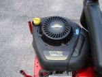
Background: I had been given this mower around 2000 with a leaky 8HP Briggs. I replaced that engine with a 12HP Briggs that lasted up until this past season. That engine lost compression and "dropped" an intake valve. Being the end of the season I did the old "steak" the valve seat to finish out the leaf season. Worked but knew it was time to redo the engine.
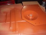
So I removed the old Briggs and didn't stop... All the pieces for the mower are in boxes. I'm starting with the mower and will work on the deck in the next phase. It is amazing how easy and well built these machines are (OK, were). I'm currently waiting on parts and doing all the cleaning in a modified HF parts washer. Stay tuned for more...
Thanks, Matt
#2

Boobala
OK ....... Now , lets see some pics..
Boobala
Hello all,
I've always found great info on forums so I'll add my experience (or lack of) with restoring a Snapper RER 28085S that was given to me by my father-in-law. I already have it in pieces so I'll start the build up there. I think most can take things apart? It's getting them back together that's the problem ;o)
Model: Snapper RER 28085S 28" HiVac w/low profile bagger
Background: I had been given this mower around 2000 with a leaky 8HP Briggs. I replaced that engine with a 12HP Briggs that lasted up until this past season. That engine lost compression and "dropped" an intake valve. Being the end of the season I did the old "steak" the valve seat to finish out the leaf season. Worked but knew it was time to redo the engine.
So I removed the old Briggs and didn't stop... All the pieces for the mower are in boxes. I'm starting with the mower and will work on the deck in the next phase. It is amazing how easy and well built these machines are (OK, were). I'm currently waiting on parts and doing all the cleaning in a modified HF parts washer. Stay tuned for more...
Thanks, Matt
OK ....... Now , lets see some pics..
#3
J
Jack17
J
Jack17
“My mama always said, ‘[Snapper rider] is like a box of chocolates. You never know what you’re gonna get.'”-Forrest
#4

mattm55


mattm55
I have some pictures of the disassembled Snapper. I will be restoring in two phases. The (1) rider and the (2) deck.
Thanks, Matt
Thanks, Matt
Attachments
#5

NorthBama
NorthBama
that guy from Mississippi sure speaks strange language
Nice work thanks for the pictures
Nice work thanks for the pictures
#7

NorthBama
He not from Mississippi that's for sure
NorthBama
I don't suppose he's from Mississippi. Hong Kong...maybe?
He not from Mississippi that's for sure
#8

Boobala
Boobala
Looks like a nice start on your project Matt , keep the pics & up-dates coming .. Boobala ..:thumbsup:
#9

mattm55
mattm55
OK. I thought he was giving me some tips and tricks, like a model # for "shocks"?
"5.990.000Ä‘ nay còn shock hÆ¡n vá»›i quÃ* tặng"
Anyhow, thanks. As I keep cleaning the parts I find a few more things I need to order (gear shifter handle and chain case bearings are notchy). Once the weather warms up a slight bit here in the northeast I can start painting. In progress assembly pics will be forthcoming....
Thanks, Matt
#11

mattm55
mattm55
I'm still waiting for a few parts for the rear end and the weather in the northeast to warm up for painting. Yesterday I did get to press in the new rear axle bushings. I used a HF 20 ton press with a set of HF Maddox 10pc Bearing Race and Seal driver kit. The HF stuff works great for this small stuff.

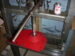
Progress....


Progress....
#13

mattm55
mattm55
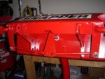
OK. I have the heater working in the garage so I can get my pieces primed and painted. Using Rustoleum Gloss Cherry Red for the topcoat.
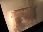
Making progress and hopefully I'll get the case and front end prepped and painted. I'm thinking I can get the main case into the blast cabinet? Hopefully....
Matt
Making progress and hopefully I'll get the case and front end prepped and painted. I'm thinking I can get the main case into the blast cabinet? Hopefully....
Matt
#16

mattm55
mattm55
Progress being made...
Edit: I also want to credit "jimsfixitshop" videos that I'm referencing. He's got a nice 7 part series rebuilding the Snapper RER. While mentioned below I find things a little different in assembly from his to mine. For those differences, I'll point them out for my 1985 28" Snapper in the forum.
1. I have the chain case all together. Nothing out of the ordinary but I did have some extra play in the hub & sprocket (3/16"). I used my 20 ton press to reshape the case to remove the extra end play. I thought about using shims from the old spacers but the press worked for me.
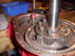
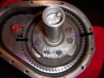
2. Moving on to the differential, I am following a video which omits a few parts from my build actually. A thrust washer in particular below the 63 tooth gear. I am overriding the video with the manual and parts diagrams whenever necessary. In the diff rebuild, I'm doing the "extra tuff" mod. I am using 8 gears instead of the 4 from the original. I did notice that there are alignment marks to line up with on the gear and top plate as shown in the pic. I haven't noticed any references to these alignment marks online so I wanted to point them out.
3. I gave the wrong color of Rustoleum I was using in a prior post. I am using Rustoleum "Regal Red" which is a little darker than original but pretty close. I am colorblind to red and green though (testing only) ;o)
Matt
#19

mattm55
mattm55
While starting to assemble the Snapper's rear axle I came across a couple of things I have to repair now. Pictures forthcoming...
Matt
- Rear Axle End Play: After getting both of the fenders attached temporarily, I have noticed the usual end play with the axle. I have a few of the nylon spacers but have a gap a little over 1/4". The next step is to take some aluminum round stock I have and make a spacer. Once complete, I'll post pics.
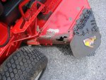
- Yoke Play: Upon putting the yoke back on I noticed that one of the holes on the case was out of round. Quite a bit of play for the nylon bushing. I should have seen this before but I missed it. So that will take some thinking on the best way to repair. I don't want to let it go as this will effect the drive disk to clutch effectiveness. I've gone this far... why not. My first idea is to round the hole out with a step drill and then tig weld a zinc washer in the hole and then grind and redrill to the correct size. Maybe another idea. One good thing is putting all the tools to use.... ;o)
*I see I wasn't the only one with this issue. I haven't found any other references using G**GLE for it either.
http://www.lawnmowerforum.com/showthread.php/11777-Snapper-rear-engine-rider-yoke-bearing-fix?highlight=yoke+play
Matt
#20

mattm55
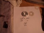
Here is my rear axle spacer from a piece of aluminum round stock I had turned on a Grizzly G0602 variable speed lathe. I wanted to create a spacer thick enough so I could remove the nylon spacers for the initial build. As everything wears, I'll have the nylon spacers to put back in.
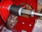
Progress... now I have to see about welding up the yoke mount next.
Matt
mattm55
- Rear Axle End Play: After getting both of the fenders attached temporarily, I have noticed the usual end play with the axle. I have a few of the nylon spacers but have a gap a little over 1/4". The next step is to take some aluminum round stock I have and make a spacer. Once complete, I'll post pics.
Here is my rear axle spacer from a piece of aluminum round stock I had turned on a Grizzly G0602 variable speed lathe. I wanted to create a spacer thick enough so I could remove the nylon spacers for the initial build. As everything wears, I'll have the nylon spacers to put back in.


Progress... now I have to see about welding up the yoke mount next.
Matt
#22

mattm55
So the first image shows just how much the yoke attachment is out of round.
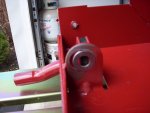
My intentions were to Tig weld the hole up but then have to grind away the washers. I went with "Plan B" which was to take a sheet of (1/8") 0.125" steel and fabricate an angled yoke holder. I bent the steel 90 degrees and step drilled a 0.803" hole for the nylon bearing. I then turned a 0.125" thick nylon spacer for the extra width. The new bracket is attached by 2 5/16" bolts through the back. By doing the repair this way I figured I could always replace the angle if it gets worn over welding and keeping the stability of the original bracket for alignment and strength. I think it should work and take up the play.
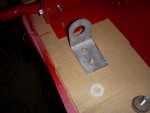
*Note: On the original yoke attachment where the bend is up from the back of the machine I had to grind/remove the ridge that kept the new bracket from being positioned right up against the original mount.

While the paint dries on the new yoke bracket, I continued putting the rear axle back in.
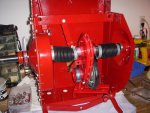
More to come...
mattm55
...
Matt
- Yoke Play: Upon putting the yoke back on I noticed that one of the holes on the case was out of round. Quite a bit of play for the nylon bushing. I should have seen this before but I missed it. So that will take some thinking on the best way to repair. I don't want to let it go as this will effect the drive disk to clutch effectiveness. I've gone this far... why not. My first idea is to round the hole out with a step drill and then tig weld a zinc washer in the hole and then grind and redrill to the correct size. Maybe another idea. One good thing is putting all the tools to use....
So the first image shows just how much the yoke attachment is out of round.

My intentions were to Tig weld the hole up but then have to grind away the washers. I went with "Plan B" which was to take a sheet of (1/8") 0.125" steel and fabricate an angled yoke holder. I bent the steel 90 degrees and step drilled a 0.803" hole for the nylon bearing. I then turned a 0.125" thick nylon spacer for the extra width. The new bracket is attached by 2 5/16" bolts through the back. By doing the repair this way I figured I could always replace the angle if it gets worn over welding and keeping the stability of the original bracket for alignment and strength. I think it should work and take up the play.

*Note: On the original yoke attachment where the bend is up from the back of the machine I had to grind/remove the ridge that kept the new bracket from being positioned right up against the original mount.

While the paint dries on the new yoke bracket, I continued putting the rear axle back in.

More to come...
#23

mattm55
mattm55
Just a few updates to the build...
*One thing I did notice while searching the internet is that while my yoke mounts are cut out/bent from the main case as one piece, there are models where Snapper used a yoke mount bracket similar to my fix but all one piece (both sides). So if this happens again, I might look for that part #.
Thanks for watching
- Rear Axle Boot: OK, mental note to not slather a ton of grease on the hex tube. If you do, or over do, make sure the ends of the boots stay clean. Otherwise you will have the boot want to slip off under extended travel. On, off, clean, rinse and repeat. I had one side just not cooperating!
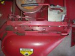
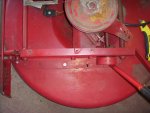
- Brake & Clutch Cables: I googled trying to find some diagrams of the connections and routing of each cable. Nothing gave a clear picture of how they are connected. Lucky I had the forethought to snap a few images on disassembly. Maybe not the complete route but enough to get it close. Here are the before pics on my model.
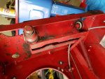
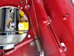
- Front End: Working on installing the front end back on the machine with tie rods/king pins and steering. I'll post pics when this step is completed.
*One thing I did notice while searching the internet is that while my yoke mounts are cut out/bent from the main case as one piece, there are models where Snapper used a yoke mount bracket similar to my fix but all one piece (both sides). So if this happens again, I might look for that part #.
Thanks for watching
#24

Boobala
Boobala
Looking great Matt,
waaaay back , I was repairing a Volvo marine outdrive.... fortuneatly for me, ... a fellow that had done this before .... had his wife ( a hobbyist photographer ) take pictures of EVERYTHING he did , with explicit close-ups on EVERYTHING . He loaned me those photos ( which shamed those in the FACTORY repair manuaI I was using )
needless to say it was a piece of cake for me. From that point on I always took pics of ALMOST everything I worked on but used a shoulder held camcorder in those days on a tripod.. finally digital cameras became affordable Amen ! And as they say the rest is history... slow me down ..??? a little ... but when I DID NEED a reference there
it was .... I save all my photos to thumb drives and keep them organized (usually) ..(LOL) I for one truly love to see the progress in pics ... keep em coming ..later my friend ...Boobala
#25

mattm55
Thanks for the kudos.
Yes, I have done quite a few projects with pics and videos found on the web. I appreciate all those who have done so before me and giving tips and tricks. That's why I taking a little extra time and posting here to maybe someday help someone after me.
Thanks, Matt
mattm55
Looking great Matt,
waaaay back , I was repairing a Volvo marine outdrive.... fortuneatly for me, ... a fellow that had done this before .... had his wife ( a hobbyist photographer ) take pictures of EVERYTHING he did , with explicit close-ups on EVERYTHING . He loaned me those photos ( which shamed those in the FACTORY repair manuaI I was using )
needless to say it was a piece of cake for me. From that point on I always took pics of ALMOST everything I worked on but used a shoulder held camcorder in those days on a tripod.. finally digital cameras became affordable Amen ! And as they say the rest is history... slow me down ..??? a little ... but when I DID NEED a reference there
it was .... I save all my photos to thumb drives and keep them organized (usually) ..(LOL) I for one truly love to see the progress in pics ... keep em coming ..later my friend ...Boobala
Thanks for the kudos.
Yes, I have done quite a few projects with pics and videos found on the web. I appreciate all those who have done so before me and giving tips and tricks. That's why I taking a little extra time and posting here to maybe someday help someone after me.
Thanks, Matt
#26

mattm55
mattm55
Progress...
Now I'll have to get some 5/16"x24 studs for the engine as two mounting holes are threaded. Stay tuned for more updates.
Matt
- Main Chassis:
Things are going back together pretty smoothly. The Aux Brake cable I had to think about but with the images and some of the web's videos I did get it routed correctly.
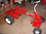
- Engine Pre Mounting:
SO for the engine, I needed to recheck to see if the mounting locations are the same. Otherwise I would either have to redrill or make a new mounting plate. It looks like the 11Hp Briggs and the Honda GXV390-DE have the same mounting holes and crankshaft location, as shown.
11HP Briggs
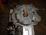
Briggs Mounting
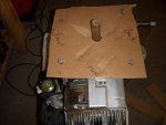
Honda Mounting Check is the same as the Briggs. Great!
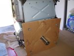
Now I'll have to get some 5/16"x24 studs for the engine as two mounting holes are threaded. Stay tuned for more updates.
Matt
#27

Boobala
Any issue with crank diameter or length ...?? LOOKING GOOD Matt !!
Boobala
Progress...
- Main Chassis:
Things are going back together pretty smoothly. The Aux Brake cable I had to think about but with the images and some of the web's videos I did get it routed correctly.
View attachment 31573
- Engine Pre Mounting:
SO for the engine, I needed to recheck to see if the mounting locations are the same. Otherwise I would either have to redrill or make a new mounting plate. It looks like the 11Hp Briggs and the Honda GXV390-DE have the same mounting holes and crankshaft location, as shown.
11HP Briggs
View attachment 31572
Briggs Mounting
View attachment 31571
Honda Mounting Check is the same as the Briggs. Great!
View attachment 31570
Now I'll have to get some 5/16"x24 studs for the engine as two mounting holes are threaded. Stay tuned for more updates.
Matt
Any issue with crank diameter or length ...?? LOOKING GOOD Matt !!
#28

mattm55
Yes, good call but I had checked that prior to buying the Honda.
Briggs and Stratton 28v707-113-E2
1"x3 5/32" shaft
Honda GVX390
1" x 3 5/32" shaft
7/16-20 tapped
Here are the specs.
Key Specs:
10.2hp GXV390
GX Series
Overhead Valve Design: Yes
Cast Iron Cylinder Sleeve: Yes
Mounting: Vertical
Electric Start: 12V Starter (with pull start)
Oil Capacity: 1.16 Qt w/o oil filter, 1.48 Qt with oil filter
Oil Type: Summer: 10W-30 Winter: 5W-30
Fuel Tank: 3 Quart
Shaft Size: 1"Dx3-5/32"L
Muffler: Included
Length: 12.5"
Height: 15.5"
Width: 14"
Shipping Weight: 100.5
mattm55
Any issue with crank diameter or length ...?? LOOKING GOOD Matt !!
Yes, good call but I had checked that prior to buying the Honda.
Briggs and Stratton 28v707-113-E2
1"x3 5/32" shaft
Honda GVX390
1" x 3 5/32" shaft
7/16-20 tapped
Here are the specs.
Key Specs:
10.2hp GXV390
GX Series
Overhead Valve Design: Yes
Cast Iron Cylinder Sleeve: Yes
Mounting: Vertical
Electric Start: 12V Starter (with pull start)
Oil Capacity: 1.16 Qt w/o oil filter, 1.48 Qt with oil filter
Oil Type: Summer: 10W-30 Winter: 5W-30
Fuel Tank: 3 Quart
Shaft Size: 1"Dx3-5/32"L
Muffler: Included
Length: 12.5"
Height: 15.5"
Width: 14"
Shipping Weight: 100.5
#29

mattm55
Going back to my first post, this Snapper has had an 8HP Briggs and then was updated to a 12HP I/C Briggs. The latest fell victim to overheating and "dropping" an intake seat. Up to this point there has been minor updates to the build that I have tried to explain. Now, the engine change from Briggs to Honda should take a little bit of modding to get installed. Some of the areas of concern are
mattm55
Model: Snapper RER 28085S 28" HiVac w/low profile bagger
Background: I had been given this mower around 2000 with a leaky 8HP Briggs. I replaced that engine with a 12HP Briggs that lasted up until this past season. That engine lost compression and "dropped" an intake valve. Being the end of the season I did the old "steak" the valve seat to finish out the leaf season. Worked but knew it was time to redo the engine.
Going back to my first post, this Snapper has had an 8HP Briggs and then was updated to a 12HP I/C Briggs. The latest fell victim to overheating and "dropping" an intake seat. Up to this point there has been minor updates to the build that I have tried to explain. Now, the engine change from Briggs to Honda should take a little bit of modding to get installed. Some of the areas of concern are
- Fitment and shaft location and size - So far the GVX390 measures up to fit in the exact mounting holes with the same shaft size and dia. I created a mock template of the old Briggs to make sure the shaft location is similar. It was in the same location. If it wasn't, I would have had to redrill mounting holes to get the shaft placement correct. Otherwise the gears 1,2,3,4,5 & R would be off. One note is that the Honda has 2 threaded holes so I purchase (2) A: 5/16"x24X1.5" by B: 5/16"x18X9/16" studs and installed them with two nuts and loctite.
- Controls - TBD (Ordered 7075089YP)
- Electrical - TBD
- Fuel - TBD (To use the original Snapper tank or the Honda engine mounted tank.)
- Exhaust - TBD (Plan is to create a side exhaust as the Honda exhausts out back and I have a bagger)
#30

Boobala
Ahhh decisions, decisions, decisions...... Ya know matt , sometimes it's a good thing to just set a chair a ways back from your project ... open a cold one and RELAX ... take a break ... and marvel at what you have accomplished thus far !!
Then you can visualize what if ...??? I do this ..THAT way ..YEAH go ahead ... YOU deserve it ... and there's always tomorrow . ..:biggrin:
Boobala
Going back to my first post, this Snapper has had an 8HP Briggs and then was updated to a 12HP I/C Briggs. The latest fell victim to overheating and "dropping" an intake seat. Up to this point there has been minor updates to the build that I have tried to explain. Now, the engine change from Briggs to Honda should take a little bit of modding to get installed. Some of the areas of concern are
- Fitment and shaft location and size - So far the GVX390 measures up to fit in the exact mounting holes with the same shaft size and dia. I created a mock template of the old Briggs to make sure the shaft location is similar. It was in the same location. If it wasn't, I would have had to redrill mounting holes to get the shaft placement correct. Otherwise the gears 1,2,3,4,5 & R would be off. One note is that the Honda has 2 threaded holes so I purchase (2) A: 5/16"x24X1.5" by B: 5/16"x18X9/16" studs and installed them with two nuts and loctite.
- Controls - TBD (Ordered 7075089YP)
- Electrical - TBD
- Fuel - TBD (To use the original Snapper tank or the Honda engine mounted tank.)
- Exhaust - TBD (Plan is to create a side exhaust as the Honda exhausts out back and I have a bagger)
Ahhh decisions, decisions, decisions...... Ya know matt , sometimes it's a good thing to just set a chair a ways back from your project ... open a cold one and RELAX ... take a break ... and marvel at what you have accomplished thus far !!
Then you can visualize what if ...??? I do this ..THAT way ..YEAH go ahead ... YOU deserve it ... and there's always tomorrow . ..:biggrin:
#31

mattm55
Yes, I have done that on many occasions. Sometimes sleeping on it helps clear your mind and offers betters ways of solving a problem. I keep telling myself, over and over, it's just a lawnmower. The first cut of the season will take that newness out of it pronto. And I do hear the grass waking up from a cold winters nap (upstate NY) so time is running short. "TSSST".
"TSSST - ...the sound of a beer can opening/a vocal attempt to reenact the sound of a beer can opening." ;o)
mattm55
Ahhh decisions, decisions, decisions...... Ya know matt , sometimes it's a good thing to just set a chair a ways back from your project ... open a cold one and RELAX ... take a break ... and marvel at what you have accomplished thus far !!
Then you can visualize what if ...??? I do this ..THAT way ..YEAH go ahead ... YOU deserve it ... and there's always tomorrow . ..:biggrin:
Yes, I have done that on many occasions. Sometimes sleeping on it helps clear your mind and offers betters ways of solving a problem. I keep telling myself, over and over, it's just a lawnmower. The first cut of the season will take that newness out of it pronto. And I do hear the grass waking up from a cold winters nap (upstate NY) so time is running short. "TSSST".
"TSSST - ...the sound of a beer can opening/a vocal attempt to reenact the sound of a beer can opening." ;o)
#32

Boobala
I get it... you enjoy my friend ....ENJOY !!!
Boobala
Yes, I have done that on many occasions. Sometimes sleeping on it helps clear your mind and offers betters ways of solving a problem. I keep telling myself, over and over, it's just a lawnmower. The first cut of the season will take that newness out of it pronto. And I do hear the grass waking up from a cold winters nap (upstate NY) so time is running short. "TSSST".
"TSSST - ...the sound of a beer can opening/a vocal attempt to reenact the sound of a beer can opening." ;o)
I get it... you enjoy my friend ....ENJOY !!!
#33

mattm55
mattm55
Thanks for others who have done the Briggs to Honda repower...
The throttle hookup from the Briggs to Honda needs to be modified. The original Briggs cable is about 14" long as shown in the image below.
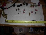
The cable attached to the Briggs engine horizontally where the Honda will be located vertically. I ordered Part#7075089YP which is the Honda throttle cable. This cable is about 39" long.
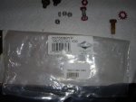
Since the mount on the Honda throttle cable was top mounted with 2 screws I decided to take my original throttle handle (side mount) and remove the short cable (straighten z-bend) and replace with the longer 39" cable and bending the z-bend. That way I have my original side mount but with a longer cable. You could just find the longer cable instead of buying the handle and save $. I also added another 10x32 screw in my handle to make it more secure and not want to rotate as the Honda's extended travel is tighter and caused the handle to move.
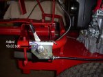
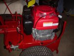
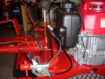
For the routing of the cable I initially had it looping on the outside but decided to reroute the cable towrds the tank indent so it wouldn't be caught on anything and pull out.
Matt
The throttle hookup from the Briggs to Honda needs to be modified. The original Briggs cable is about 14" long as shown in the image below.

The cable attached to the Briggs engine horizontally where the Honda will be located vertically. I ordered Part#7075089YP which is the Honda throttle cable. This cable is about 39" long.

Since the mount on the Honda throttle cable was top mounted with 2 screws I decided to take my original throttle handle (side mount) and remove the short cable (straighten z-bend) and replace with the longer 39" cable and bending the z-bend. That way I have my original side mount but with a longer cable. You could just find the longer cable instead of buying the handle and save $. I also added another 10x32 screw in my handle to make it more secure and not want to rotate as the Honda's extended travel is tighter and caused the handle to move.

For the routing of the cable I initially had it looping on the outside but decided to reroute the cable towrds the tank indent so it wouldn't be caught on anything and pull out.


Matt
#35

mattm55
mattm55
I'm starting on the electrical wiring and in parallel I wanted to start on the 2nd phase of the build. The cutting deck needs to be disassembled, cleaned, painted and reassembled.
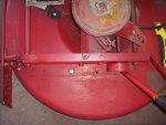
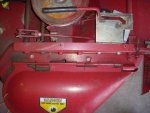
*An impact gun definitely helps with disassembly of the main pulley nut and the blade bar nut. These are on there quite tight. The blade bar is also threaded on so once you remove the nut you need to unscrew the blade bar. My spindle bearings are in good shape so I won't be replacing those.
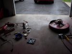
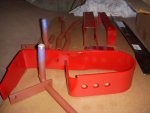
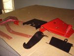
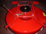
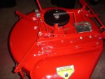
A pile of bead blasted parts ready for primer and paint. The deck I'll have to do by hand as that is the only part that won't fit into my cabinet.
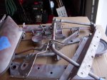
Matt


*An impact gun definitely helps with disassembly of the main pulley nut and the blade bar nut. These are on there quite tight. The blade bar is also threaded on so once you remove the nut you need to unscrew the blade bar. My spindle bearings are in good shape so I won't be replacing those.

A pile of bead blasted parts ready for primer and paint. The deck I'll have to do by hand as that is the only part that won't fit into my cabinet.

Matt
#37

mattm55
Thanks for sharing. I like the way they (Snapper) updated the cutting height bar on yours. The one I have takes a good amount of effort to raise and lower. I also like the cup holder location. I asked my wife where she wanted it located (she rides while I push) and she said up on the steering. I may offer her that location even though we have the second pedal.
Thanks.
mattm55
Ran across these pics ...thought you might enjoy....
View attachment 31650...View attachment 31651...View attachment 31652
...View attachment 31654...View attachment 31655
View attachment 31656...View attachment 31657
Got one of my murray pics in there somehow.. cant delete it ..SORRY !!
Thanks for sharing. I like the way they (Snapper) updated the cutting height bar on yours. The one I have takes a good amount of effort to raise and lower. I also like the cup holder location. I asked my wife where she wanted it located (she rides while I push) and she said up on the steering. I may offer her that location even though we have the second pedal.
Thanks.
#38

mattm55
mattm55
While waiting for the paint to dry on the deck and deck parts I started working on the electrical wiring of the Snapper. I decided to eliminate the interlock for the cutting deck but kept the interlock for the Park safety switch. It's more likely to try to start in gear than have a start situation with the blade moving.
One other thing is that I am removing the "push button" start and replacing it with a key start so I won't have to reach back and push that button.
Parts List:
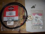
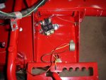
I found that the pre-built wiring harness made an easy job as it connects directly to the ignition switch with the ground wire included. This routes thru the tube and has enough wire to make it to the "electrical junction box" area.
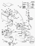
Since there seems to be very little on the wiring layout on the internet I will do a simple diagram of how I wired mine up with images to come. I am using this schematic as a good starting reference.
Thanks, Matt
One other thing is that I am removing the "push button" start and replacing it with a key start so I won't have to reach back and push that button.
Parts List:
- Wiring Harness: 7074062YP
- Ignition Switch (4 pole): 7073997YP
- Wire: 16AWG different colors or tape, 6AWG (red & black) for load to battery off solenoid
- Connectors: 16AWG & 6AWG
- Solenoid (4 pole): A generic solenoid with 3 or 4 poles from AMZ for $10.
- In-line Fuse: 10 amp in-line fuse block


I found that the pre-built wiring harness made an easy job as it connects directly to the ignition switch with the ground wire included. This routes thru the tube and has enough wire to make it to the "electrical junction box" area.
Since there seems to be very little on the wiring layout on the internet I will do a simple diagram of how I wired mine up with images to come. I am using this schematic as a good starting reference.

Thanks, Matt
#39

mattm55
mattm55
Here is a simple wiring diagram for the Snapper Honda GXV-390 repower.

1. In my haste I didn't realize the Honda already had a solenoid next to the starter. I already had a generic solenoid mounted and decided to use mine, In the case it ever goes bad, I'll switch over to the Honda's. So in my diagram I only used the Honda's solenoid lug that went to the starter.
2. In my diagram I did not show the inline 10 A fuse on the Battery side of my solenoid. If you need me to draw or explain, just send me an email. It's pretty simple to add.
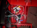
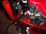
Matt

1. In my haste I didn't realize the Honda already had a solenoid next to the starter. I already had a generic solenoid mounted and decided to use mine, In the case it ever goes bad, I'll switch over to the Honda's. So in my diagram I only used the Honda's solenoid lug that went to the starter.
2. In my diagram I did not show the inline 10 A fuse on the Battery side of my solenoid. If you need me to draw or explain, just send me an email. It's pretty simple to add.


Matt
#41

mattm55
mattm55
I made quite a bit of progress over the weekend...
1. Installed the deck back onto the main frame.
2. Installed a fresh belt and adjusted the tension to slip enough when cutter not engaged. I had to loosen the tube clamp and make the adjustments to the belt and then recheck that all my pedals had enough free play with the tube being moved back about 1/4". I didn't have to add an adjustments to the cable .
3. A new blade and lift kit was installed.
4. Adjusted the shift linkage so that neutral and park lined up in the correct location.
*On my engine drive disk I had made a nice tool on the recommendations on the internet and manual I downloaded. The 3 3/4" - 3 13/16" distance did not work for me. That was way too low so I had to improvise and set it by feel. I let the drive disk touch the disk and then moved the pedal throw to get a little more pressure. For me, the distance was set at ~3.5". I will try it and adjust as necessary/wear.
5. Mounted the bottle holder to the steering column.
6. Added gas and oil (38.2 oz of 10w30)
7. Connected charged battery
All done right? Well, as I tried to start the engine there was nothing. Hmm, ahh... the parking switch had to be on and I just had it in the neutral position. Nope, still nothing. Time to get out the meter and recheck my connections. When I pulled the box cover off I found the blue solenoid wire came off. Connected that and voila.... she runs! Success.
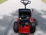
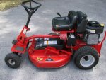
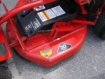
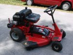
I took a few pictures in the garage after a test run...
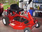
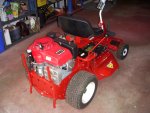
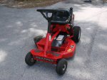
...and a few passes cutting. Then out in the front for a few pics to close out this build.
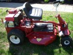
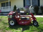
Everything went pretty smooth and the Briggs to Honda conversion was almost bolt on. Not too bad for a 32 year old mower.
If anyone has any questions, just let me know.
Now it will be on to cutting the grass.
Thanks for following my build.
Matt
1. Installed the deck back onto the main frame.
2. Installed a fresh belt and adjusted the tension to slip enough when cutter not engaged. I had to loosen the tube clamp and make the adjustments to the belt and then recheck that all my pedals had enough free play with the tube being moved back about 1/4". I didn't have to add an adjustments to the cable .
3. A new blade and lift kit was installed.
4. Adjusted the shift linkage so that neutral and park lined up in the correct location.
*On my engine drive disk I had made a nice tool on the recommendations on the internet and manual I downloaded. The 3 3/4" - 3 13/16" distance did not work for me. That was way too low so I had to improvise and set it by feel. I let the drive disk touch the disk and then moved the pedal throw to get a little more pressure. For me, the distance was set at ~3.5". I will try it and adjust as necessary/wear.
5. Mounted the bottle holder to the steering column.
6. Added gas and oil (38.2 oz of 10w30)
7. Connected charged battery
All done right? Well, as I tried to start the engine there was nothing. Hmm, ahh... the parking switch had to be on and I just had it in the neutral position. Nope, still nothing. Time to get out the meter and recheck my connections. When I pulled the box cover off I found the blue solenoid wire came off. Connected that and voila.... she runs! Success.
I took a few pictures in the garage after a test run...


...and a few passes cutting. Then out in the front for a few pics to close out this build.


Everything went pretty smooth and the Briggs to Honda conversion was almost bolt on. Not too bad for a 32 year old mower.
If anyone has any questions, just let me know.
Now it will be on to cutting the grass.
Thanks for following my build.
Matt
#42

Boobala
Boobala
CONGRATS !! Matt
A really nice machine , time to grab that seat again... get a cold drink and reminisce about all the obstacles you overcame and the results you derived from your labor !!
THANKS for sharing, and the photos were great too ! Don't forget to visit ........ Boobala ..:thumbsup:
A really nice machine , time to grab that seat again... get a cold drink and reminisce about all the obstacles you overcame and the results you derived from your labor !!
THANKS for sharing, and the photos were great too ! Don't forget to visit ........ Boobala ..:thumbsup:
#43

mattm55
Thanks for watching and the comments. I did put out the table and chairs on the deck Sunday here as the weather was beautiful. That's about all the time for relaxing as I start on the next project. Finishing a Sno-Way (plow) install on my Tacoma. I had a rush install for the 2' snow in March and bypassed hooking up the lights. Now if I wait until fall I'll keep putting it off. My wife is looking at washing windows too....
There never seems to be a lack of projects to work on. ;o)
...and of course, I won't forget to visit.
Thanks, Matt
mattm55
CONGRATS !! Matt
A really nice machine , time to grab that seat again... get a cold drink and reminisce about all the obstacles you overcame and the results you derived from your labor !!
THANKS for sharing, and the photos were great too ! Don't forget to visit ........ Boobala ..:thumbsup:
Thanks for watching and the comments. I did put out the table and chairs on the deck Sunday here as the weather was beautiful. That's about all the time for relaxing as I start on the next project. Finishing a Sno-Way (plow) install on my Tacoma. I had a rush install for the 2' snow in March and bypassed hooking up the lights. Now if I wait until fall I'll keep putting it off. My wife is looking at washing windows too....
There never seems to be a lack of projects to work on. ;o)
...and of course, I won't forget to visit.
Thanks, Matt

