rajthepilot
Member
- Joined
- Jun 1, 2023
- Threads
- 13
- Messages
- 48
In a forum 2 days, I requested some help regarding my mower's wiring. 'StarTech' was kind to help me with the diagram. I then spent hours looking at it and following my mower's wiring to make sense of it all and then I wrote down what I learn, to help diagnose it now and also in the future. I'm posting what I learned here, so hopefully it helps some one else as well. I'm posting in multiple messages as it's very long. I do have one question about the wiring diagram that I couldn't figure out. When the ignition is off, G & M & A at the ignition switch are connected. But what purpose does it serve to connect the A?

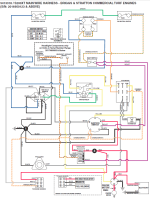
Now I will describe my understanding of the Wiring Schematic Diagram of Snapper Pro S200XT Zero Turn Mower with a Briggs & Stratton Engine
The 'Time Delay Module Schematic' shown in the upper section of the diagram. Top left is 2, Bottom Left is 1, Bottom Right is 3, Middle Right is 4, Top Right is 5. Ports 2 and 5 always have continuity, unless 12 volts DC are given to Ports 1 and 3, then Ports 2 and 4 are immediately connected. If current stops, there is about a 1 to 2 second lag before connection shifts from Ports 2 to 4 TO Ports 2 to 5.
Time delay module - seat delay - ignition delay - I think are all the same thing (please correct me if I’m wrong)
The time delay module is below the seat switch and towards the right side of the mower on the Snapper Pro S200XT
The 'Starter Relay' is below the seat switch on the Snapper Pro S200XT and towards the left side of the mower. - If current passes between Blue 86 and Green 85, then it makes a connection between Yellow 30 and Yellow 87, otherwise the yellow wires have an open circuit
Both Starter Relay and Time Delay Module are hard to reach in the Snapper Pro S200XT, but then again so is most of the wiring, including the solenoid, the oil filter. Everything is in tight spaces.
Ignition Switch has 7 wires coming out of it, but 6 connections, M, L, S, B, A & G (2 of L are connected to same prong / port). As the diagram shows on top left. If key is in 'Off' Position, G & M & A are connected. If key in 'Run' position, then B & L & A are connected and if key in 'Start' position, then B & L &S are connected.
M is for Magneto (White Wire). If Magneto is connected to Ground, it causes a short circuit and stops it from working, it won't send electricity to spark plug to produce sparks. S is Starting, B is from Battery, G is Ground, L ports have 2 wires coming out, one of them powers the Fuel Solenoid (also known as anti back fire valve, located at the base of the carburetor – I got this form a youtube video -
). When 12VDC (volts direct current) is applied, that allows the flow of fuel to the main jet of the carburetor). The other wire from L goes through a series of safety switches to power the Starting Relay, and A powers the PTO
Based on the wiring diagram, if you're in the "Run" key position, you should hear a click if engaging the PTO (the engine doesn't need to be running)
If PTO button is engaged / pulled up, "S" wire won't get power to the starting solenoid to start the engine.
When key is off, M & G & A are connected. (I’m not sure why A is connected)
Magneto (aka ignition coil). If connected to negative battery terminal, it'll stop it from working.
The Top of the Diagram shows 'LH Neutral Switch' and 'RH Neutral Switch". These switches are on the left and right side of the Ground Speed Levers. When you push them outwards, the levers push those switches and close the circuit. When you pull them in to drive, the circuits become open.
PTO switch has 8 prongs. One side has 3, middle has 3, one side has 2. When PTO is disengaged, "pushed in", then the outer sides (3 prongs and 2 prongs) are connected. When it is engaged (pulled up), the 3 outer prongs are connected with 3 inner prongs.
When testing, you're testing "flat" to "flat" meaning the prongs that are parallel to each other, not side by side. So if you see prongs like this "=" these are parallel, and if you see this "- -" these are not. You would test "=" (top and bottom) and not "- -" (side by side) with each other for continuity using multimeter. Some switches just have "=" and some have "= =". When you have 4 prongs, it means two will have continuity when not pressed and two will have it when pressed. If you have "=" (I'm trying to mimic the shape of the prongs), then they'll have continuity when the button is pressed. Press it slowly, so you can check if it has any dead spots. If you have 4 parallel, then you test outer and inner.
Parking Switch - The position in the diagram shows when the parking switch is disengaged, lever down. You also have to rotate it 180 degrees, and that's how I see it when I pick up the seat on the Snapper Pro S200XT. The orange/green wires are on the top.
So if the parking switch is engaged (lever up), Orange from the PTO connects to Orange/Green and Blue disconnects from Orange / Green. When parking is disengaged (lever down), Blue connects to Orange / Green and Orange disconnects from Orange / Green
Seat Switch: The diagram shows Normally Closed, NC, and it is closed if you're sitting on the seat and the button is depressed. Then the two orange / green wires on the left are connected to the two violet wires on the right in the diagram. The violet wires are connected with each other, so current can go freely through them. The orange / green are also connected with each other and currently can move freely through them, but when the seat switch is depressed (when you're sitting it), now both sides are connected as well. In the mower, below the seat. The purple wires are facing front and orange / green wires are facing the rear of the mower.
Seat Switch only has 2 prongs, one has two violets connected and the other has two orange / green connected. If you sit on the seat, all four of these are connected.
The Seat Switch in diagram shows "NC", normal closed (NO is normally open). This is closed if you're sitting on it.
Solenoid: In the diagram, it is at the bottom right, just above starting motor and left of the battery (it's not labeled there). If the small yellow and black wire have 12 volts DC, then the big red wires are connected, letting current go from the battery's red terminal to the starting motor's red terminal. The negative of the starter is connected to the engine frame itself and the frame is connected to the battery's negative ground.
You can have a 3 post solenoid or 4 post. Snapper Pro S200XT has a 4 post. In 3 post, the small wire 12v ground in a 4 post is now the frame itself in the 3 post.
On a solenoid, it doesn't matter which way the big red ones are hooked up as they're just joined by solenoid and doesn't matter which way the small ones are hooked up (that bring 12VDC to join the big ones)
So let's run through multiple scenario and show the direction of current (positive to negative - current flow, not electron flow). It's very interesting how this all works, and please correct me if I’m wrong in any of the scenarios. I will correct my notes that I keep at home
Scenario 1: Key is "Off"
Ignition Switch G & M & A are connected. M is connected to Ground. M is a white wire connected to ground at the ignition switch now. It then goes to port 5 of Time Delay module, but it also continues onwards to the magnetos. It is directly connected at Port 5, both white wires are connected at Port 5 (meaning they're connected with each other) This causes a short circuit in the magneto and it will not work, there will be no sparks in the spark plug, if the engine turns.
I don't understand why the A is also connected to Ground when the key is in "Off" position, what purpose does that serve?
Now I will describe my understanding of the Wiring Schematic Diagram of Snapper Pro S200XT Zero Turn Mower with a Briggs & Stratton Engine
The 'Time Delay Module Schematic' shown in the upper section of the diagram. Top left is 2, Bottom Left is 1, Bottom Right is 3, Middle Right is 4, Top Right is 5. Ports 2 and 5 always have continuity, unless 12 volts DC are given to Ports 1 and 3, then Ports 2 and 4 are immediately connected. If current stops, there is about a 1 to 2 second lag before connection shifts from Ports 2 to 4 TO Ports 2 to 5.
Time delay module - seat delay - ignition delay - I think are all the same thing (please correct me if I’m wrong)
The time delay module is below the seat switch and towards the right side of the mower on the Snapper Pro S200XT
The 'Starter Relay' is below the seat switch on the Snapper Pro S200XT and towards the left side of the mower. - If current passes between Blue 86 and Green 85, then it makes a connection between Yellow 30 and Yellow 87, otherwise the yellow wires have an open circuit
Both Starter Relay and Time Delay Module are hard to reach in the Snapper Pro S200XT, but then again so is most of the wiring, including the solenoid, the oil filter. Everything is in tight spaces.
Ignition Switch has 7 wires coming out of it, but 6 connections, M, L, S, B, A & G (2 of L are connected to same prong / port). As the diagram shows on top left. If key is in 'Off' Position, G & M & A are connected. If key in 'Run' position, then B & L & A are connected and if key in 'Start' position, then B & L &S are connected.
M is for Magneto (White Wire). If Magneto is connected to Ground, it causes a short circuit and stops it from working, it won't send electricity to spark plug to produce sparks. S is Starting, B is from Battery, G is Ground, L ports have 2 wires coming out, one of them powers the Fuel Solenoid (also known as anti back fire valve, located at the base of the carburetor – I got this form a youtube video -
Based on the wiring diagram, if you're in the "Run" key position, you should hear a click if engaging the PTO (the engine doesn't need to be running)
If PTO button is engaged / pulled up, "S" wire won't get power to the starting solenoid to start the engine.
When key is off, M & G & A are connected. (I’m not sure why A is connected)
Magneto (aka ignition coil). If connected to negative battery terminal, it'll stop it from working.
The Top of the Diagram shows 'LH Neutral Switch' and 'RH Neutral Switch". These switches are on the left and right side of the Ground Speed Levers. When you push them outwards, the levers push those switches and close the circuit. When you pull them in to drive, the circuits become open.
PTO switch has 8 prongs. One side has 3, middle has 3, one side has 2. When PTO is disengaged, "pushed in", then the outer sides (3 prongs and 2 prongs) are connected. When it is engaged (pulled up), the 3 outer prongs are connected with 3 inner prongs.
When testing, you're testing "flat" to "flat" meaning the prongs that are parallel to each other, not side by side. So if you see prongs like this "=" these are parallel, and if you see this "- -" these are not. You would test "=" (top and bottom) and not "- -" (side by side) with each other for continuity using multimeter. Some switches just have "=" and some have "= =". When you have 4 prongs, it means two will have continuity when not pressed and two will have it when pressed. If you have "=" (I'm trying to mimic the shape of the prongs), then they'll have continuity when the button is pressed. Press it slowly, so you can check if it has any dead spots. If you have 4 parallel, then you test outer and inner.
Parking Switch - The position in the diagram shows when the parking switch is disengaged, lever down. You also have to rotate it 180 degrees, and that's how I see it when I pick up the seat on the Snapper Pro S200XT. The orange/green wires are on the top.
So if the parking switch is engaged (lever up), Orange from the PTO connects to Orange/Green and Blue disconnects from Orange / Green. When parking is disengaged (lever down), Blue connects to Orange / Green and Orange disconnects from Orange / Green
Seat Switch: The diagram shows Normally Closed, NC, and it is closed if you're sitting on the seat and the button is depressed. Then the two orange / green wires on the left are connected to the two violet wires on the right in the diagram. The violet wires are connected with each other, so current can go freely through them. The orange / green are also connected with each other and currently can move freely through them, but when the seat switch is depressed (when you're sitting it), now both sides are connected as well. In the mower, below the seat. The purple wires are facing front and orange / green wires are facing the rear of the mower.
Seat Switch only has 2 prongs, one has two violets connected and the other has two orange / green connected. If you sit on the seat, all four of these are connected.
The Seat Switch in diagram shows "NC", normal closed (NO is normally open). This is closed if you're sitting on it.
Solenoid: In the diagram, it is at the bottom right, just above starting motor and left of the battery (it's not labeled there). If the small yellow and black wire have 12 volts DC, then the big red wires are connected, letting current go from the battery's red terminal to the starting motor's red terminal. The negative of the starter is connected to the engine frame itself and the frame is connected to the battery's negative ground.
You can have a 3 post solenoid or 4 post. Snapper Pro S200XT has a 4 post. In 3 post, the small wire 12v ground in a 4 post is now the frame itself in the 3 post.
On a solenoid, it doesn't matter which way the big red ones are hooked up as they're just joined by solenoid and doesn't matter which way the small ones are hooked up (that bring 12VDC to join the big ones)
So let's run through multiple scenario and show the direction of current (positive to negative - current flow, not electron flow). It's very interesting how this all works, and please correct me if I’m wrong in any of the scenarios. I will correct my notes that I keep at home
Scenario 1: Key is "Off"
Ignition Switch G & M & A are connected. M is connected to Ground. M is a white wire connected to ground at the ignition switch now. It then goes to port 5 of Time Delay module, but it also continues onwards to the magnetos. It is directly connected at Port 5, both white wires are connected at Port 5 (meaning they're connected with each other) This causes a short circuit in the magneto and it will not work, there will be no sparks in the spark plug, if the engine turns.
I don't understand why the A is also connected to Ground when the key is in "Off" position, what purpose does that serve?