You are using an out of date browser. It may not display this or other websites correctly.
You should upgrade or use an alternative browser.
You should upgrade or use an alternative browser.
Export thread
Scag Ignition Relay
#1
H
Hayward51
H
Hayward51
Hey Folks, I'm back to working on my Tiger Cub I rebuilt last summer. I posted questions in September about rewiring because of PO rigged the wired and did away with all safety switches. I'm still trying to figure out how the safeties all work through the harness. Today's question is ...does Scag use a particular relay for the ignition ? I'm thinking the relay is not working as it should. I bought one from the local AutoZ and it doesn't send 12V on Green/White wire to the solenoid as diagrams show. Wires on the relay are correct according to diagrams. The PO cut into the Green wire, which is hot when switched to start, and ran wire to solenoid. Am I wrong thinking that the relay should switch from one terminal (86) through electromagnet to proper terminal (87) when 12V are applied ? AS you may can tell, I'm confused to say the least. Thanks for any suggestions ...
#2

StarTech
StarTech
Post Model and Serial again so someone can pull the correct wiring diagram. But so far the one diagram I pulled no relay used for the ignition system.
#3
H
Hayward51
H
Hayward51
This is 2002 Tiger Cub STC 48A 20CV s# 7640064. I had to dig for the wiring diagrams I have. The manual diagram isn't much help.Post Model and Serial again so someone can pull the correct wiring diagram. But so far the one diagram I pulled no relay used for the ignition system.
#5
H
Hayward51
H
Hayward51
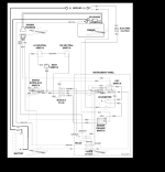
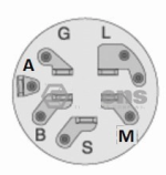
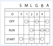
Thanks for your reply. I have this diagram. Not the switch make/break table. All seems to be wired correctly with Green wire from switch to relay HOT when key to start. I don't understand how it gets to the Green/White (stripe) wire going to the engine harness. If I ground Green/Black (stripe) wire at the start, it connects to GreenWhite to engine. I'm assuming this happens through the safety interface module.?? Does this mean I have a bad module ?
#6

StarTech
StarTech
Not necessarily. Especially when someone has hacked the harness. The interlock module is controlled by the lay bar switches along brake, PTO, and seat switches.
Part of the problem is that interlock module is kinda of mystery box. Scag doesn't tell us how is configed inside. Apparently it need 12v to operate so there must be a relay type switch inside that grounds the green/black wire when safeties satisfies the circuit logic sequence. Personally I could rewire to a grounding logic setup removing the need for 12v to control the module but it would hard for to explain it remotely as I haven't done or needed to do the Scag interlock module bypass here just the JD ZTR ones. It is like doing heart bypass surgery you got to know what you doing at the time of the bypassing.
Just take your time an trace out the circuit making sure all the switches are working as intended.
#7
H
Hayward51
H
Hayward51
Not necessarily. Especially when someone has hacked the harness. The interlock module is controlled by the lay bar switches along brake, PTO, and seat switches.
Part of the problem is that interlock module is kinda of mystery box. Scag doesn't tell us how is configed inside. Apparently it need 12v to operate so there must be a relay type switch inside that grounds the green/black wire when safeties satisfies the circuit logic sequence. Personally I could rewire to a grounding logic setup removing the need for 12v to control the module but it would hard for to explain it remotely as I haven't done or needed to do the Scag interlock module bypass here just the JD ZTR ones. It is like doing heart bypass surgery you got to know what you doing at the time of the bypassing.
Just take your time an trace out the circuit making sure all the switches are working as intended.
#8
H
Hayward51
H
Hayward51
I have verified that all safety switches are good. Looking at the diagram for a 5 pole relay, it shows that the terminal the green/black wire attached to is (or should be) grounded. I have the relay grounded. All this is very confusing to me but I would like to get the safety features working.
#9

StarTech
StarTech
Currently according the schematic Scag is using (feeding) 12v through safety switches and the interlock then converts this to a grounding circuit for the starter relay. In order to delete the interlock module the system would need to be converted to a grounding system.
This requires removing the red jumper wire from pole C to pole A on the PTO. Now disconnect the lt blue wire from the other pole C terminal and attach a ground to the terminal. Now at the interlock module disconnect the Orange, and the Green/Black wires. Tie those two wires together. The only left is get the seat to kill ignition if you are off the seat. This would require disconnecting the Brown and White wires from the interlock module and tying them together. Note don't do this unless the circuit is converted to a grounding or you will fry your ignition coils but only if the brake switch is activated. But I would prefer the seat to kill the engine anytime you are not on the seat so I remove the red wire at the seat switch and attach a ground to the ground terminal. This way whenever the operator is not present the mower will not run. (just in case operator get knock off the seat when mowing). And yes I had one customer that had someone to mis-wired his mower, it did happen, and the mower took out his wife's new car. Let's there was someone hunting him.
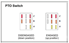
Quite easy to do when you know what you are doing but can be confusing to those that don't. So please don't try this unless are 100% sure know what you are doing.
This requires removing the red jumper wire from pole C to pole A on the PTO. Now disconnect the lt blue wire from the other pole C terminal and attach a ground to the terminal. Now at the interlock module disconnect the Orange, and the Green/Black wires. Tie those two wires together. The only left is get the seat to kill ignition if you are off the seat. This would require disconnecting the Brown and White wires from the interlock module and tying them together. Note don't do this unless the circuit is converted to a grounding or you will fry your ignition coils but only if the brake switch is activated. But I would prefer the seat to kill the engine anytime you are not on the seat so I remove the red wire at the seat switch and attach a ground to the ground terminal. This way whenever the operator is not present the mower will not run. (just in case operator get knock off the seat when mowing). And yes I had one customer that had someone to mis-wired his mower, it did happen, and the mower took out his wife's new car. Let's there was someone hunting him.

Quite easy to do when you know what you are doing but can be confusing to those that don't. So please don't try this unless are 100% sure know what you are doing.
#10
H
Hayward51
H
Hayward51
Thank you for those instructions. I will study the wiring to familiarize myself thoroughly before snipping. BTW, the PO also removed the seat switch and connected the wires together. I'll have to replace the switch and plug.Currently according the schematic Scag is using (feeding) 12v through safety switches and the interlock then converts this to a grounding circuit for the starter relay. In order to delete the interlock module the system would need to be converted to a grounding system.
This requires removing the red jumper wire from pole C to pole A on the PTO. Now disconnect the lt blue wire from the other pole C terminal and attach a ground to the terminal. Now at the interlock module disconnect the Orange, and the Green/Black wires. Tie those two wires together. The only left is get the seat to kill ignition if you are off the seat. This would require disconnecting the Brown and White wires from the interlock module and tying them together. Note don't do this unless the circuit is converted to a grounding or you will fry your ignition coils but only if the brake switch is activated. But I would prefer the seat to kill the engine anytime you are not on the seat so I remove the red wire at the seat switch and attach a ground to the ground terminal. This way whenever the operator is not present the mower will not run. (just in case operator get knock off the seat when mowing). And yes I had one customer that had someone to mis-wired his mower, it did happen, and the mower took out his wife's new car. Let's there was someone hunting him.
View attachment 67902
Quite easy to do when you know what you are doing but can be confusing to those that don't. So please don't try this unless are 100% sure know what you are doing.
#11

StarTech
StarTech
KInda figured the PO might have done that. People think safeties are there to be a pain. It is like those bypass the mow in reverse inhibitors. Since 2009 I have heard of two cases in my area where toddlers have been ran over by the mower operator. One resulted in the child death and the other the little girl lost part her foot.
I simply will not bypass safeties and customer that want me to do it can go somewhere else.
I simply will not bypass safeties and customer that want me to do it can go somewhere else.
#12
H
Hayward51
H
Hayward51
I have ordered the seat switch with bracket. I won't expect it within a week (hopefully sooner) but I most probably will be back here with questions and to let you know how it works out. Thank you for your input, Star Tech.KInda figured the PO might have done that. People think safeties are there to be a pain. It is like those bypass the mow in reverse inhibitors. Since 2009 I have heard of two cases in my area where toddlers have been ran over by the mower operator. One resulted in the child death and the other the little girl lost part her foot.
I simply will not bypass safeties and customer that want me to do it can go somewhere else.
#13
H
Hayward51
H
Hayward51
Star Tech, One major question on my mind (yes, it's confusing), when you say "don't do this unless the circuit is converted to a grounding", what exactly determines that the circuit is grounding ? I'm assuming it's the rewiring of the PTO switch. ?? I just want to have this part straight in my mind when I get the seat switch installed.Currently according the schematic Scag is using (feeding) 12v through safety switches and the interlock then converts this to a grounding circuit for the starter relay. In order to delete the interlock module the system would need to be converted to a grounding system.
This requires removing the red jumper wire from pole C to pole A on the PTO. Now disconnect the lt blue wire from the other pole C terminal and attach a ground to the terminal. Now at the interlock module disconnect the Orange, and the Green/Black wires. Tie those two wires together. The only left is get the seat to kill ignition if you are off the seat. This would require disconnecting the Brown and White wires from the interlock module and tying them together. Note don't do this unless the circuit is converted to a grounding or you will fry your ignition coils but only if the brake switch is activated. But I would prefer the seat to kill the engine anytime you are not on the seat so I remove the red wire at the seat switch and attach a ground to the ground terminal. This way whenever the operator is not present the mower will not run. (just in case operator get knock off the seat when mowing). And yes I had one customer that had someone to mis-wired his mower, it did happen, and the mower took out his wife's new car. Let's there was someone hunting him.
View attachment 67902
Quite easy to do when you know what you are doing but can be confusing to those that don't. So please don't try this unless are 100% sure know what you are doing.
#15
H
Hayward51
H
Hayward51
I'm sorry to seem too dense to comprehend your reply but, "means you do not (x) to be applying (x) to the ignition coil kill terminal", sounds like a word or two are missing in this statement.It means you do not to be applying to the ignition coil kill terminal. The enclosed electronics will not survive if you do.
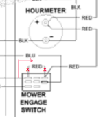
This why the 12v jumper is removed at the PTO switch and then the terminal is connected to ground. Items in red are the changes at the PTO switch.
View attachment 67913
#16

StarTech
StarTech
Sorry I forgot to proofread my post. I do have a bad habit of thinking faster than I type. Plus I am on a fluid restriction so I hadn't my coffee yet. It had to manage 1.5 liters per day.I'm sorry to seem too dense to comprehend your reply but, "means you do not (x) to be applying (x) to the ignition coil kill terminal", sounds like a word or two are missing in this statement.
It should read "It means you do not want to be applying 12V to the ignition coil."It means you do not to be applying to the ignition coil kill terminal.
#17
H
Hayward51
H
Hayward51
Star Tech, I got my seat switch in and started my rewiring of the Scag. I read thoroughly and when I got to the seat switch part, I found I have 2 RED wires and a BROWN wire going to the switch. One red goes to hour meter and one red goes to the PTO switch. I had 12V on one of those red wires before I rewired, now none. I connected the terminal C (lt blue wire) to ground, turned key ON, and blew a fuse. I noticed the seat switch wiring on different year model diagram (SN 9260001-926999) is the same as my harness wiring. This threw me ! Could the PO have used another harness be the reasoning behind hacking the wiring ??
#18

StarTech
StarTech
It possible but it should not caused the problem.
Okay I might missed a wire here. Try simply disconnecting the interlock module. It might be that the pink wire is causing the problem at the interlock along with the hour meter power feed.
It looks like they might rewired the hour meter to get it 12v thru the interlock and the seat switch. Unplugging the interlock should stop this. Note the interlock module is the same on both SN.
#19
H
Hayward51
I disconnected the interlock module turned key ON, blew another fuse ??
H
Hayward51
When I got to the part about grounding the red wire at the seat switch is when I noticed I had 2 red wires. That part was most confusing of all. How does that switch work if disconnected ? And is it necessary after disconnecting module ?It possible but it should not caused the problem.
Okay I might missed a wire here. Try simply disconnecting the interlock module. It might be that the pink wire is causing the problem at the interlock along with the hour meter power feed.
It looks like they might rewired the hour meter to get it 12v thru the interlock and the seat switch. Unplugging the interlock should stop this. Note the interlock module is the same on both SN.
I disconnected the interlock module turned key ON, blew another fuse ??
#20

StarTech
StarTech
Boy do I wish I was at the mower myself. So hard to explain things remotely. Something is still connecting to +12v which getting grounded and blowing the fuse.
#21
H
Hayward51
H
Hayward51
I was trying to figure it out myself but I still don't understand how the grounding system works. I toned the Pink wire just to make sure it was going to the parking brake. The tone wouldn't run on the grounded wire until I released the brake. I assumed a wire past that switch had it grounded. I wish you were around also, mainly to explain how this works. I'm at a stand still. Can you give me a hint on how to determine the fault ??Boy do I wish I was at the mower myself. So hard to explain things remotely. Something is still connecting to +12v which getting grounded and blowing the fuse.
#22
H
Hayward51
H
Hayward51
Star Tech, if I knew more about the gounding system, I would continue myself and not bother you any further. I'm at a loss not knowing and would like to know how to test for the 12V without blowing fuses. I do appreciate your input.I was trying to figure it out myself but I still don't understand how the grounding system works. I toned the Pink wire just to make sure it was going to the parking brake. The tone wouldn't run on the grounded wire until I released the brake. I assumed a wire past that switch had it grounded. I wish you were around also, mainly to explain how this works. I'm at a stand still. Can you give me a hint on how to determine the fault ??
#23

StarTech
StarTech
Well the old way I use before they banned them was to use an 100w incandescent light bulb. But it is resettable circuit breakers that works to save fuses. They even come in auto reset versions.
Auto reset Fuses (circuit breakers)
I usually don't worry replacing fuses as I get off Amazon dirt cheap.
Bulk ATC Fuses
Auto reset Fuses (circuit breakers)
I usually don't worry replacing fuses as I get off Amazon dirt cheap.
Bulk ATC Fuses
#24
H
Hayward51
H
Hayward51
It's not the cost of fuses that worries me. IF I can get the 12V to stay on long enough to find the wire, what do I do with the 12V wire ? Ground it ?Well the old way I use before they banned them was to use an 100w incandescent light bulb. But it is resettable circuit breakers that works to save fuses. They even come in auto reset versions.
Auto reset Fuses (circuit breakers)
I usually don't worry replacing fuses as I get off Amazon dirt cheap.
Bulk ATC Fuses
#25

StarTech
StarTech
That's where the old light bulb was so handy as it lit brightly during shorts and you could disconnect things until it lit dimly. You need to disconnect 12 v wire but first you got find why it is coming from to cause the short to ground.

