D
Deleted member 97405
Guest
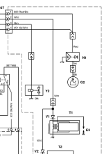
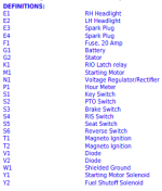
Sometime in the past, the metal bracket that keeps the PTO clutch from spinning probably wore through, and when the clutch spun around, it tore all the wiring out. I've seen it a bunch of times. Can create an electrical nightmare. I hope you get it figured out. It's a fairly simple system. But word of advice, find that metal bracket. It's secured to the side of the tractor frame with one bolt and goes in and keeps the PTO body stationary. If that bracket has any wear at all, replace it. It's fairly cheap and will save you from an expensive electrical repair. Anytime I get this series in the shop, I make it a habit to check that bracket. Cant tell you how many grateful customers I've saved a ton of money over the years...The serial number tag has worn off unfortunately. The guy I'm looking at it for had "hot wired" it and I am pretty sure he cut out a wire or 2. I can get it started by jumping the solenoid (I know the solenoid needs replaced) however the blades will not engage when the PTO switch is pulled up. The PTO pigtail seems to have some connections missing.

Last edited by a moderator:


