You are using an out of date browser. It may not display this or other websites correctly.
You should upgrade or use an alternative browser.
You should upgrade or use an alternative browser.
Help! The mice got me...Z375R ZTrak Mower
- Thread starter crosby
- Start date
More options
Export threadWell then it's a safety switch, There are several to look at,
Seat
Clutch engagement
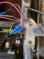
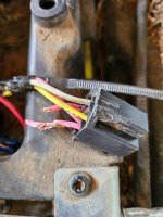
Brake for starters but looking at your pics - you'll need to chase down the mating wires for those 2 red guys - these will be on the opposite plug so find out where they go first and should get you going in the right direction
most of these switches are Normally Open circuits and get closed when satisfied but could be just the opposite depending on what their function is
- Joined
- Feb 19, 2020
- Threads
- 87
- Messages
- 11,326
Cranking Circuit Operation
Function:
To energize the starting motor to crank the engine.
Operating Conditions:
Park brake locked
PTO switch OFF
Motion control handles in NEUTRAL position
Key switch in START position
Theory of Operation:
The K1 start relay must be energized to provide power to the starter motor. The K1 start relay coil ground circuit and power circuit
are both switched. Both circuits must be completed to crank the engine.
Unswitched power is supplied to the key switch via fuse F1. (See Power Circuit Operation .) Turning the key switch to RUN or START
applies power to switch terminal A.
Power from the key switch terminal A passes through the 400A and 400B Yellow wires, F3 fuse, and 475A and 475B Yellow wires to
the P1 hour meter.
The hour meter passes power through to the 419A Yellow wire, SW2 left neutral switch, 701 Green wire, SW3 right neutral switch
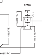
(both in the neutral position), and 608C and 608B Pink wires to the SW4 park brake switch.
With the park brake engaged, power passes through to the 605 White wire, and SW6 PTO switch terminal 3. With the PTO switch in
the OFF position power is passed through to switch terminal 9, the 702B Green wire, and SW1 key switch terminal S2
Turning the key switch to START provides power to switch terminal S1, 703 Green wire and K1 start solenoid coil.
The circuit for the start solenoid coil is completed with a ground path through the (closed) K2 interlock relay contacts. The interlock
relay coil is energized when power is passed though to the PTO switch terminal 9. Power is provided via the 702A Green wire, D3
diode, and 402C Yellow wires.
The D3 diode prevents the start solenoid from being energized if the SW6 PTO switch is in the ON position and the operator is on
the seat.
With the start solenoid energized, the main contacts close, supplying battery power to the starting motor. The spinning motor engages
the flywheel, cranking the engine.
If the ignition and fuel shutoff circuits are functioning properly, the engine starts.


